
Hypotube catheters

a catheter and hypotube technology, applied in the field of catheters, can solve the problems of limited length of microcatheters, risky use of standard angiography catheters, limited use of microcatheters, etc., and achieve the effects of increasing ease, lubricating, and smoother

Pending Publication Date: 2020-07-23
TRANSIT SCI LLC
View PDF17 Cites 3 Cited by
  • Summary
  • Abstract
  • Description
  • Claims
  • Application Information

AI Technical Summary

Benefits of technology

The hypotube and catheter in this patent have flexibility enhancing features that improve their flexibility. These features can be positioned at different locations along the hypotube and catheter to achieve different levels of flexibility in different parts of the device. The flexibility enhancing features can be used to make the catheter more flexible at its distal end, allowing it to navigate through narrow blood vessels, or to make the proximal and intermediate portions of the catheter stiffer to transmit a pushing force to the distal portion of the device. The liner of the catheter can control the flow of fluids and make the device easier to guide, insert, and remove other instruments from. It can also have a smooth surface to facilitate the movement of fluids and other materials through the device. The liner can be flexible, stretchable, and resilient to accommodate various features of the hypotube, such as expansion and contraction.

Problems solved by technology

Thus, the use of standard angiography catheters can be risky, as excessive pressures may cause such catheters to fail and, thus, may injury a subject on whom the angiography procedures is being conducted.
Because of their thin walls and small outer diameters, pushability, trackability, and torqueability requirements have limited the lengths of microcatheters.
In addition, to provide desired levels of pushability, trackability, and torqueability, microcatheters are typically tapered; stated another, way, the wall thickness and / or outer diameter is typically not uniform along the length of the microcatheter.
While stainless steel hypotubes may enhance the ability of a catheter to glide (e.g., push, track, and torque) through a subject's anatomy, they are known for their tendency to kink, particularly when forced through tortuous paths.
While nitinol hypotubes are kink-resistant, they are much more expensive to manufacture (particularly in developmental stages and in small quantities) than stainless steel hypotubes, and still lack sufficient flexibility to enable them to advance through many of the bends that are present in a subject's vasculature.

Method used


Image

  • Hypotube catheters
  • Hypotube catheters

Examples


Embodiment Construction

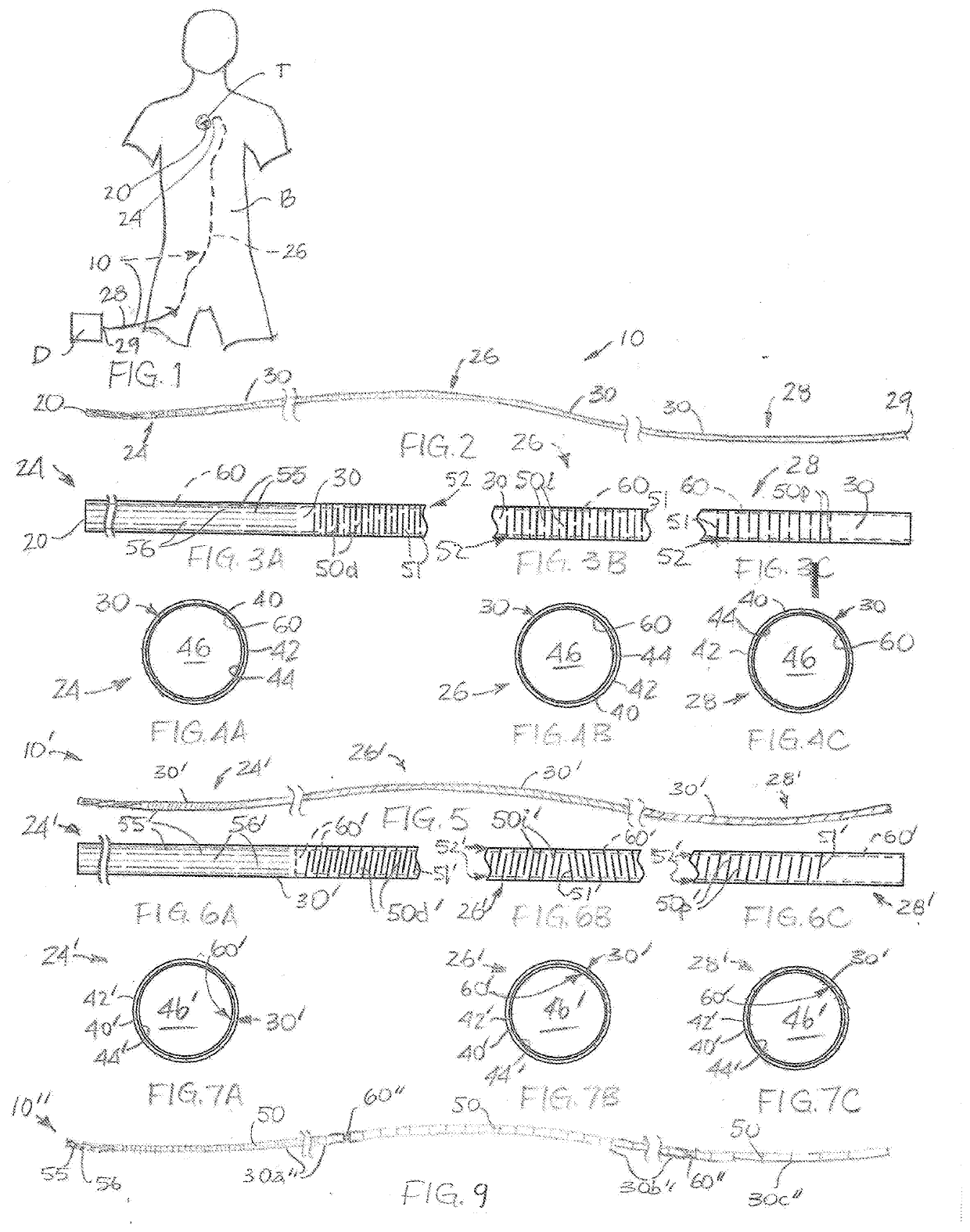
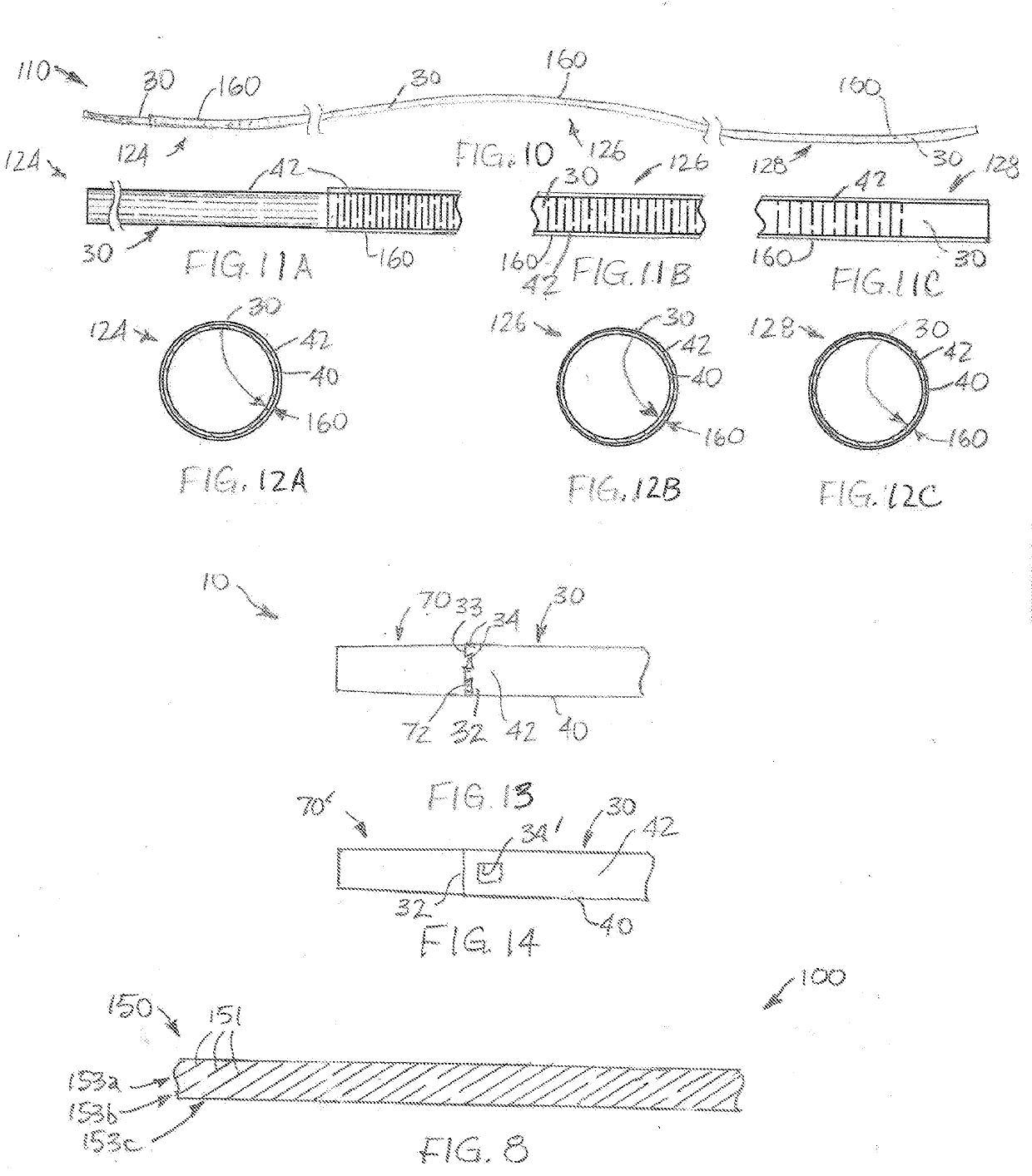
[0042]FIGS. 2-4C illustrate an embodiment of a catheter 10 that includes a hypotube 30 and a liner 60. The hypotube 30, which defines an exterior portion of a majority of a length of the catheter 10, extends along substantially an entire length of the catheter 10. The liner 60 defines an interior of a majority of the length of the catheter 10.

[0043]Along its length, the catheter 10 includes a distal end 20, a distal portion 24, an intermediate portion 26, a proximal portion 28, and a proximal end 29. As shown in FIG. 1, the distal end 20 of the catheter 10 is capable of being introduced into a body B of a subject and advanced through the body B of the subject (e.g., along a pathway, such as the subject's blood vessels, or vasculature, other vessels, or other tubes or passages) to a target site T, where a procedure is to be performed. Upon advancement of the distal end 20 to the target site T, the procedure that is to be performed may be performed using the distal end 20 or the dista...


PUM


Abstract

A catheter includes a hypotube and a liner. The hypotube may extend substantially along a length of the catheter. The liner may extend along a majority of a length of the hypotube, and may extend along substantially an entirety of the length of the hypotube. The hypotube includes flexibility enhancing features along its length. In addition, the hypotube may include one or more operational features, which may enable various procedures to be performed with the catheter. The liner may be positioned adjacent to an interior surface of a wall of the hypotube, or it may be positioned adjacent to an exterior surface of the wall of the hypotube. Any operational features of the hypotube may be exposed through or beyond a longitudinal extent of the liner or a portion thereof. Methods for manufacturing catheters that include hypotubes and liners are also disclosed.

Description

CROSS-REFERENCE TO RELATED APPLICATION[0001]Claims for the benefit of the Jan. 21, 2019 filing date of U.S. Provisional Patent Application 62 / 794,976, titled HYPOTUBE CATHETERS (“the '976 Provisional Application”) and the benefit of the Aug. 14, 2019 filing date of U.S. Provisional Patent Application 62 / 886,363, titled HYPOTUBE CATHETERS (“the '363 Provisional Application”) are hereby made pursuant to 35 U.S.C. § 119(e). The entire disclosures of the '976 Provisional Application and the '363 Provisional Application are hereby incorporated herein.TECHNICAL FIELD[0002]This disclosure relates generally to catheters and, more specifically, to catheters that are defined from hypotubes, or hypodermic tubing. This disclosure also relates to methods for manufacturing catheters and to methods for using catheters.RELATED ART[0003]Standard angiography catheters, which are typically manufactured from thermoplastic materials by extrusion processes, have pressure ratings of about 1,050 psi to abo...

Claims


Application Information

Patent Timeline
Patent Type & Authority Applications(United States)
IPC IPC(8): A61M25/01A61M25/00
CPCA61M25/0054A61M25/0138A61M2025/0024A61M25/0013A61M25/0053A61M25/0012A61M25/0069A61M25/0113
Inventor FOJTIK, SHAWN P.METHOD, GREGARNOLD, JENNIFER
Owner TRANSIT SCI LLC
Learn More