
Real time monitoring and prediction of motion in MRI

a real-time monitoring and motion prediction technology, applied in the field of magnetic resonance imaging, can solve the problems of affecting the quality of brain magnetic resonance imaging data, affecting the accuracy of mri data collection, and causing the most significant mri signal distortion,

Active Publication Date: 2020-07-16
OREGON HEALTH & SCI UNIV +1
View PDF0 Cites 13 Cited by
  • Summary
  • Abstract
  • Description
  • Claims
  • Application Information

AI Technical Summary

Benefits of technology

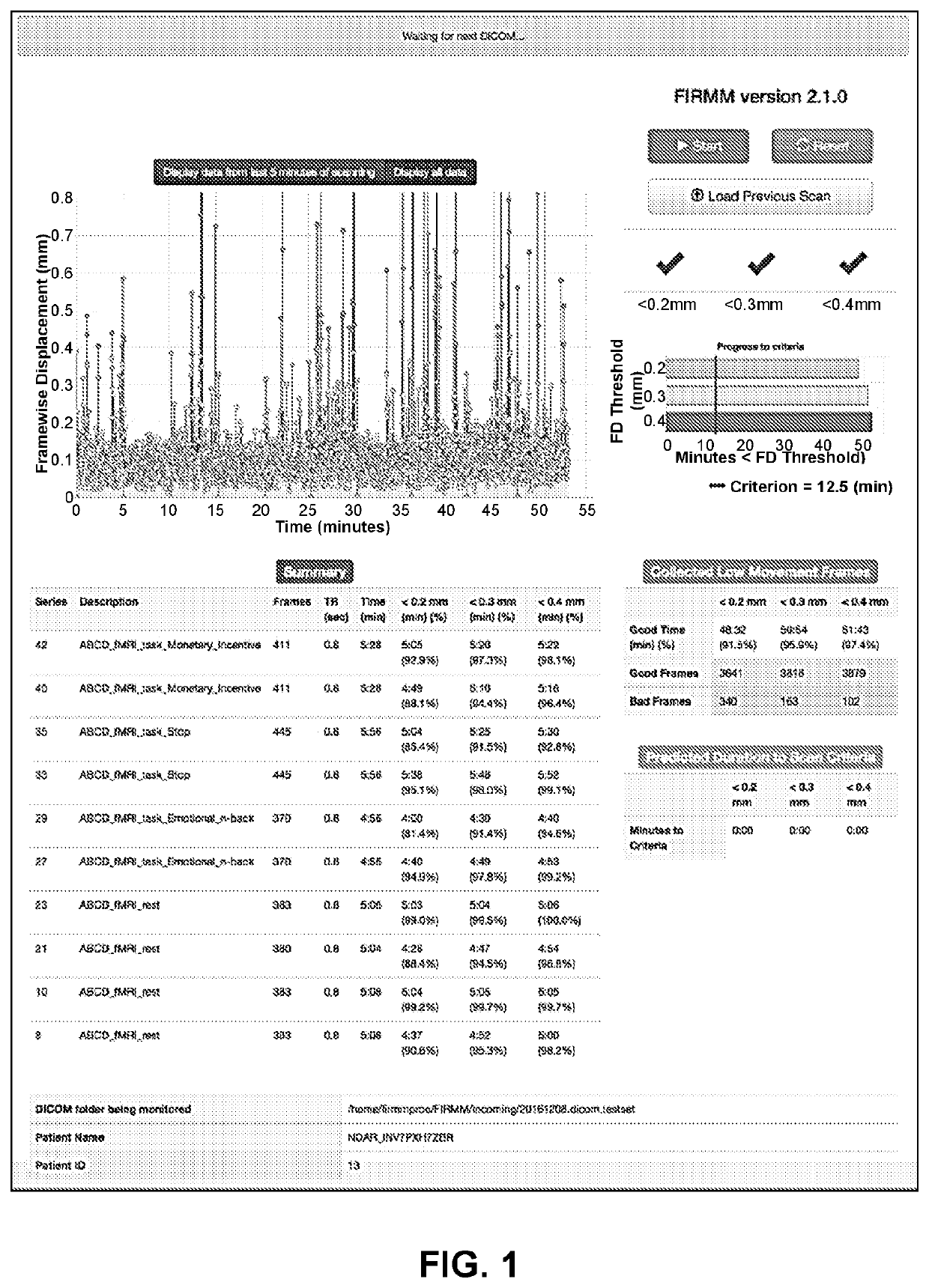
This patent describes a method for monitoring the movement of a patient during a magnetic resonance imaging (MRI) scan. The method involves aligning the MRI data to a reference image and calculating the motion of a body part between consecutive data frames using six frame alignment parameters. The total frame displacement is then display in real-time for the operator of the MRI system. This allows for improved accuracy in detecting and measuring any movement of the patient during the MRI scan.

Problems solved by technology

Body motion, such as head motion, represents the greatest obstacle to collecting quality brain Magnetic Resonance Imagining (MRI) data in humans.
Head movement from one MRI data frame to the next, rather than absolute movement away from the reference frame, is thought to induce the most significant MRI signal distortions.
Though necessary for reducing artifacts, frame censoring comes at a steep price.
If the number of frames remaining after censoring is too small, investigators may lose all data from a participant.
In order to avoid this loss, investigators typically collect additional “buffer” data, an expensive practice that, by itself, does not guarantee sufficient high-quality MRI data for a given participant.
The ‘overscanning’ required to remove motion-distorted data while maintaining sample sizes adequate to achieve a desired data quality has drastically increased the cost and duration of brain MRIs.
In this manner, structural data frames are ‘censored,’ thereby increasing the duration and cost of structural MRIs.
Unfortunately, such proxies of head movement are poorly correlated with FD because these proxies typically cannot distinguish movements of the face and scalp from brain movement.

Method used


Image

  • Real time monitoring and prediction of motion in MRI
  • Real time monitoring and prediction of motion in MRI
  • Real time monitoring and prediction of motion in MRI

Examples


example 1

Summary

[0216]The results of these experiments demonstrated the validity of the disclosed FIRMM head motion prediction method. The FIRMM head motion prediction method provides accurate real-time FD calculations, and accurate predictions in regards to the required scan time needed to reach the low movement data criterion. Further, the disclosed FIRMM head motion prediction method can be used to reduce scan times, thereby reducing the time and costs associated with ‘overscanning.’ Additionally, the FIRMM head motion prediction method further reduces scan times by enabling operators to terminate scan early for those participants who are extremely unlikely to reach the necessary low movement data criterion.

Example 2

Evaluation of FIRMM System by Scanner Operators

[0217]To evaluate the usage of the FIRMM head motion prediction method (e.g., FIRMM), described above, by scanner operators, the following experiments were conducted. After applying FIRMM to extant datasets 1 and 2, FIRMM's utilit...

example 2

Summary

[0226]The results of these experiments demonstrated the validity of usage of the disclosed FIRMM head motion prediction method by scanner operators. The FIRMM head motion prediction method alerts operators to sudden changes (e.g., increased or decreased FD values) by providing scanner operators real-time feedback by, for example, displaying data in real-time on the operator's GUI. This allows operators to respond to the feedback provided by FIRMM by taking measures to intervene during the MRI scan.

Example 3

Effect of Head Position Feedback Provided to MRI Subjects on Head Motion Using FIRMM Method

[0227]To validate the effect of providing head position feedback to MRI subjects using the FIRMM head motion prediction method described above, the following experiments were conducted. The effects of viewing movie clips, viewing a fixation crosshair (e.g., rest), and receiving real-time visual feedback about head movement during the scans were investigated in 24 participants and adol...

example 3

Summary

[0253]The results of these experiments demonstrated the validity of presenting visual feedback to a subject undergoing an MRI scan based on real-time calculations of head motion using the disclosed FIRMM head prediction method. Real-time head motion feedback, in general, reduced motion during MRI scans in young participants. Specifically, in young participants, movie watching during MRI scans reduced head motion. The results of these experiments further disclosed that movies, not feedback, significantly altered functional connectivity (FC) MRI data. Thus, real-time visual feedback may be provided by FIRMM to the subject undergoing the MRI scan by (a) changing the colors of the crosshair and (b) obstructing the movie clip with color-coded rectangles of varying sizes to allow the subject, without intervention from the scanner operator, to adjust his or her body movements accordingly.

Example 4

Identification of Respiratory Artifacts in Movement Estimates in fMRI

[0254]To identify ...


PUM


Abstract

Methods, computer-readable storage devices, and systems are described for reducing movement of a patient undergoing a magnetic resonance imaging (MRI) scan by aligning MRI data, the method implemented on a Framewise Integrated Real-time MRI Monitoring (“FIRMM”) computing device including at least one processor in communication with at least one memory device. Aspects of the method comprise receiving a data frame from the MRI system, aligning the received data frame to a preceding data frame, calculating motion of a body part between the received data frame and the preceding data frame, calculating total frame displacement, and excluding data frames with a cutoff above a pre-identified threshold of the total frame displacement.

Description

CROSS-REFERENCE TO RELATED APPLICATION[0001]This application claims priority to U.S. Provisional Application Ser. No. 62 / 468,858, filed Mar. 8, 2017, entitled REAL TIME MONITORING AND PREDICTION OF MOTION IN MRI, which is hereby incorporated in its entirety herein.ACKNOWLEDGEMENT OF GOVERNMENT SUPPORT[0002]This invention was made with government support under grants K23 NS088590, R01 MH096773, R01 MH115357, U24 DA041123, U01 DA041148, and U54 HD087011 awarded by the National Institutes of Health. The government has certain rights in the invention.FIELD[0003]The field of the disclosure involves Magnetic Resonance Imaging (MRI), and more specifically, methods for monitoring, predicting and providing feedback about patient motion in real-time during MRI.BACKGROUND[0004]Body motion, such as head motion, represents the greatest obstacle to collecting quality brain Magnetic Resonance Imagining (MRI) data in humans. Head motion distorts both structural (T1-weighted, T2-weighted, etc.) and ...

Claims


Application Information

Patent Timeline
Patent Type & Authority Applications(United States)
IPC IPC(8): G01R33/565G01R33/56G01R33/483G01R33/00A61B5/055
CPCA61B5/055G01R33/56509G01R33/5608G01R33/4831G01R33/0041A61B5/7207G16H30/40G16H40/63G16H50/70
Inventor DOSENBACH, NICOKOLLER, JONATHANVAN, ANDREWSNYDER, ABRAHAMMIRRO, AMYFAIR, DAMIENEARL, ERICKLEIN, RACHELDOMINGUEZ, OSCAR MIRANDAPERRONE, ANDERS
Owner OREGON HEALTH & SCI UNIV
Learn More