Active deck-lid spoiler control system for a motor vehicle

Active Publication Date: 2020-07-16
GM GLOBAL TECH OPERATIONS LLC
View PDF0 Cites 1 Cited by
  • Summary
  • Abstract
  • Description
  • Claims
  • Application Information

AI Technical Summary

Benefits of technology

The present disclosure is about airflow control devices for vehicles, specifically about active vehicle spoilers that are designed to minimize contaminate buildup on rear windshields of motor vehicles. The invention relates to a system that can selectively cycle the spoiler to produce downforce and improve the dynamic handling of the vehicle. The actuatable spoiler is moveable between an extended deployed position and a retracted stowed position. The system detects the vehicle's speed and uses the actuatable spoiler to optimize airflow and reduce drag. Overall, the invention helps improve the vehicle's performance and fuel economy by controlling airflow and reducing drag.

Problems solved by technology

The low-pressure zone results in increased vehicle drag, which can adversely affect the vehicle's dynamic performance and fuel economy.
For fastback type vehicles, the airflow passing over the deck-lid separates into turbulent eddies resulting in a low-pressure zone immediately behind the vehicle resulting in increased drag.
At low speeds a fixed rear spoiler may actually increase vehicle drag and does little to improve the dynamic handling of the vehicle due to having little airflow over the spoiler.

Method used


Image

  • Active deck-lid spoiler control system for a motor vehicle
  • Active deck-lid spoiler control system for a motor vehicle
  • Active deck-lid spoiler control system for a motor vehicle

Examples


Embodiment Construction

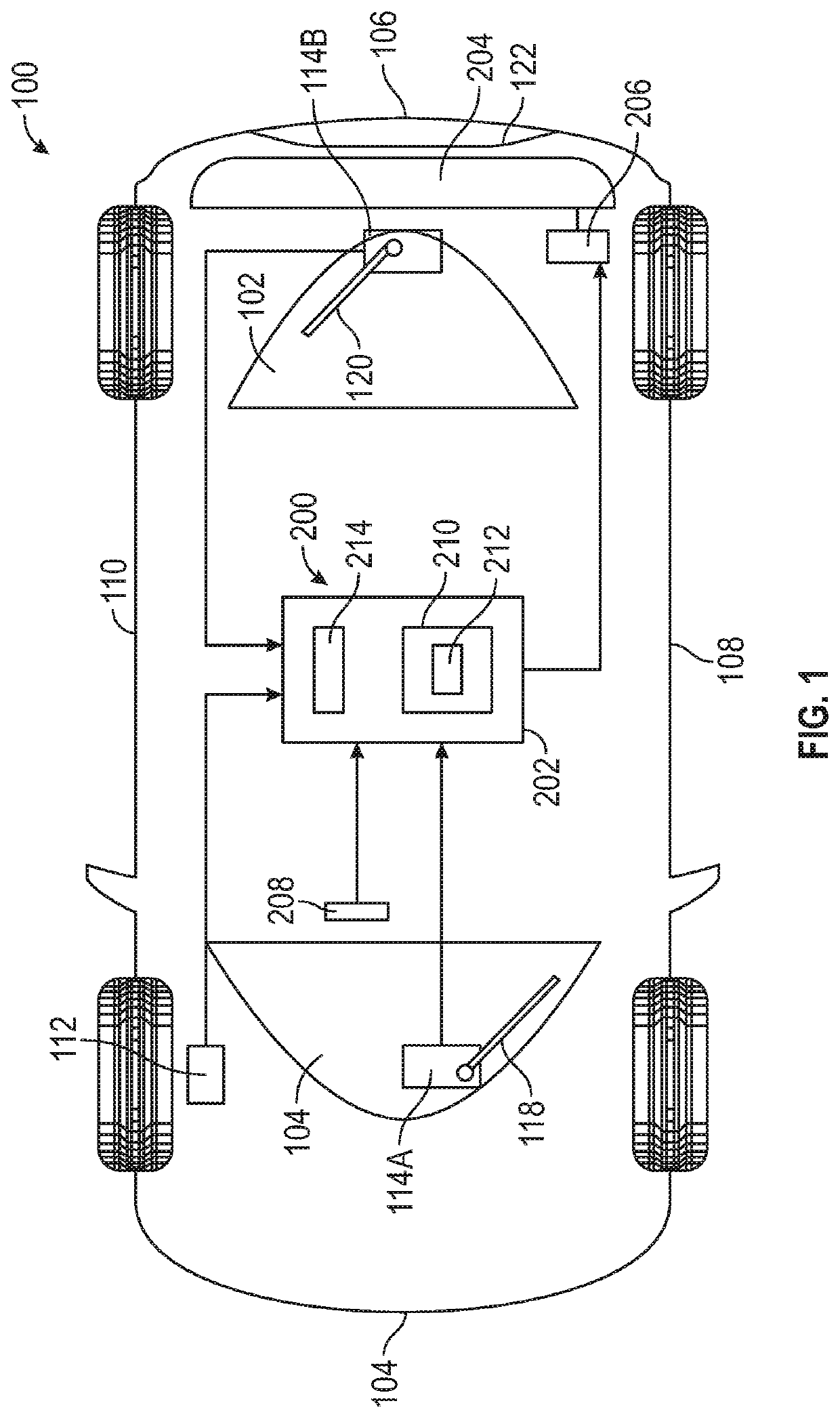
[0031]The following description is merely exemplary in nature and is not intended to limit the present disclosure, application, or uses. The illustrated embodiments are disclosed with reference to the drawings, wherein like numerals indicate corresponding parts throughout the several drawings. The figures are not necessarily to scale and some features may be exaggerated or minimized to show details of particular features. The specific structural and functional details disclosed are not intended to be interpreted as limiting, but as a representative basis for teaching one skilled in the art as to how to practice the disclosed concepts.

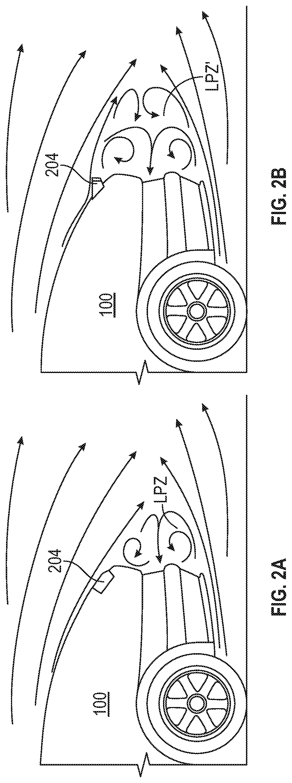
[0032]Those having ordinary skill in the art will recognize that terms such as “above,”“below,”“upward,”“downward,”“top,”“bottom,” etc., are used descriptively for the figures, and do not represent limitations on the scope of the disclosure, as defined by the appended claims. As used herein, the term “airflow” refers to the movement of air around and th...


PUM


Abstract

A vehicle having a vehicle sensor configured to detect a vehicle state; an actuatable spoiler moveable into a deployed position and a stowed position; an actuator operable to move the actuatable spoiler into the deployed position and the stowed position; and a controller configured to selectively instruct the actuator to actively cycle the actuatable spoiler between the deployed position and the stowed position based on the detected vehicle state. The actuatable spoiler is retained in the deployed position for a longer length of time than in the stowed position. The vehicle also includes a human machine interface selectively actuated by an operator of the vehicle to retain the actuatable spoiler in the stowed position for a predetermined length of time.

Description

INTRODUCTION[0001]The present disclosure relates to airflow control devices for vehicles, and more particularly, to active vehicle spoilers that are selectively cycled to minimize contaminate buildup on rear windshields of motor vehicles.[0002]A spoiler is an aerodynamic device whose intended design function is to interrupt or spoil unfavorable airflow over a vehicle body while the vehicle is motion to enhance the performance of the vehicle. Uninterrupted airflow over a vehicle body can create a low-pressure zone immediately behind the rear end of the vehicle when the vehicle is traveling at highway speeds. The low-pressure zone results in increased vehicle drag, which can adversely affect the vehicle's dynamic performance and fuel economy. This is especially true for vehicle bodies that have a gradual downward angle extending from the rear roofline down to the edge of the deck-lid of the vehicle, also known as a fastback type vehicle. For fastback type vehicles, the airflow passing...

Claims


Application Information

Patent Timeline
IPC IPC(8): B62D35/00B62D37/02F15D1/10F15D1/00
CPCF15D1/0065B62D37/02B62D35/007F15D1/10Y02T10/82B62D35/00
Inventor WELTY, MARK A.OLIVEIRA, DANILO A.
Owner GM GLOBAL TECH OPERATIONS LLC
Why Eureka
Try Eureka