Eureka AIR delivers breakthrough ideas for toughest innovation challenges, trusted by R&D personnel around the world.

Systems and methods for optimizing landing lights operation onboard an aircraft

a technology for landing lights and aircraft, applied in the direction of navigation instruments, instruments, transportation and packaging, etc., can solve the problems of increasing fuel flow, affecting flight efficiency, and affecting the operation of landing lights, so as to increase the flight efficiency level, and achieve the effect of saving costs

Inactive Publication Date: 2020-07-09
HONEYWELL INT INC
View PDF0 Cites 1 Cited by
  • Summary
  • Abstract
  • Description
  • Claims
  • Application Information

AI Technical Summary

Benefits of technology

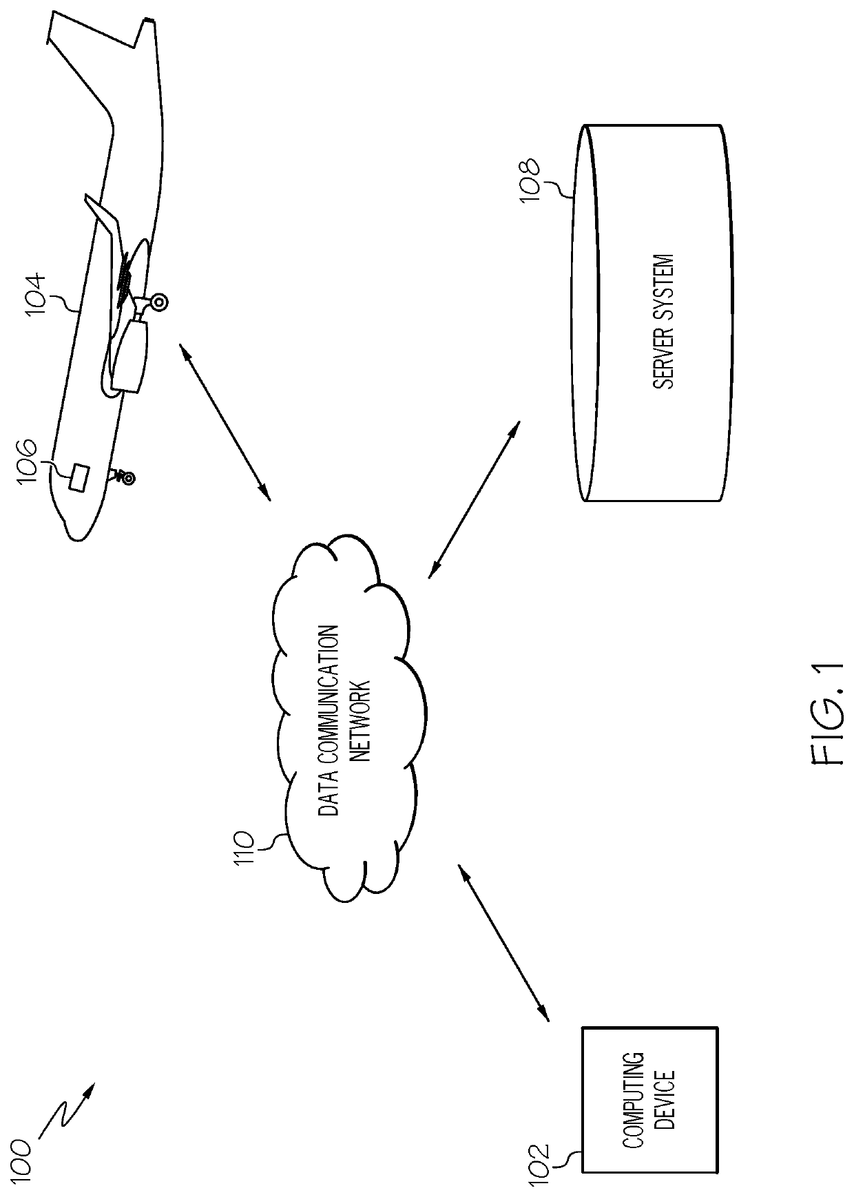
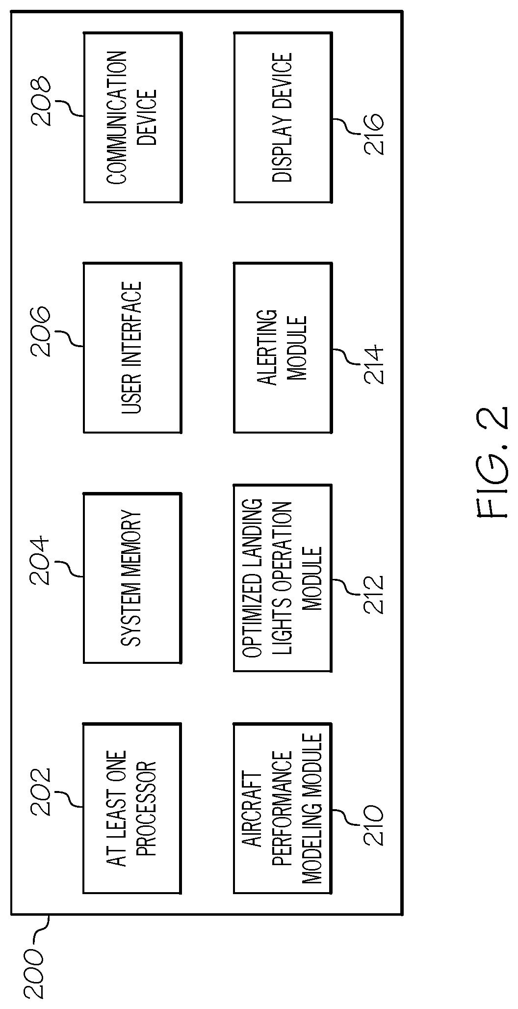
The present patent provides a method and a computing device for providing landing lights operation data during a flight of an aircraft. The method involves obtaining a standard operating procedure for operating landing lights and determining an optimized operating procedure for the landing lights based on real-time contextual data, such as aircraft data, a current state of the aircraft, and visibility requirements. The optimized operating procedure involves operating the landing lights at an optimal altitude value to increase the flight efficiency level of the aircraft, resulting in a potential cost savings. The method then presents an advisory comprising graphical elements and the increased flight efficiency level onboard the aircraft via a display device. The technical effects of this patent are improved aircraft efficiency and reduced costs associated with operating landing lights during a flight.

Problems solved by technology

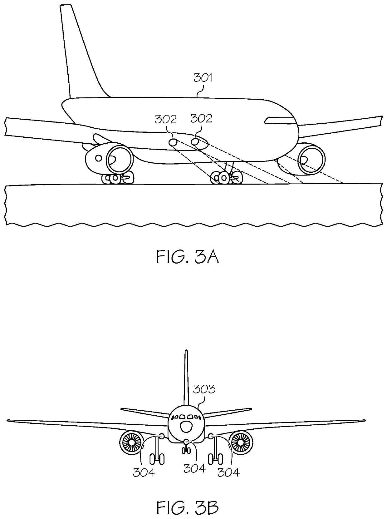
Thus, the positioning of the landing lights may disturb the airflow and add some amount of drag to the aircraft during flight.
To maintain a given aircraft speed during use of the landing lights, a slightly increased thrust is required, which results in an increased fuel flow.

Method used


Image

  • Systems and methods for optimizing landing lights operation onboard an aircraft
  • Systems and methods for optimizing landing lights operation onboard an aircraft
  • Systems and methods for optimizing landing lights operation onboard an aircraft

Examples


Embodiment Construction

[0017]The following detailed description is merely illustrative in nature and is not intended to limit the embodiments of the subject matter or the application and uses of such embodiments. As used herein, the word “exemplary” means “serving as an example, instance, or illustration.” Any implementation described herein as exemplary is not necessarily to be construed as preferred or advantageous over other implementations. Furthermore, there is no intention to be bound by any expressed or implied theory presented in the preceding technical field, background, brief summary or the following detailed description.

[0018]The subject matter presented herein relates to systems and methods for optimizing operation of the landing lights onboard an aircraft to increase flight efficiency during landing. More specifically, the subject matter relates to obtaining recommendations and standard operating procedures for landing light operation, dynamically obtaining flight data, in real-time, and dete...


PUM


Abstract

A method for providing landing lights operation data during a flight of an aircraft is provided. The method obtains a standard operating procedure (SOP) for operating landing lights onboard the aircraft during the flight, wherein the SOP comprises a customary industry-recommended practice for at least one of extension and retraction of the landing lights on the aircraft, and wherein execution of the SOP produces a flight efficiency level including at least fuel burn and drag parameters; determines an optimized operating procedure for the landing lights to increase the flight efficiency level to achieve an increased flight efficiency level, based on real-time contextual data; and presents an advisory comprising at least graphical elements associated with the optimized operating procedure, a potential cost savings for the optimized operating procedure, and the increased flight efficiency level onboard the aircraft, via a display device.

Description

TECHNICAL FIELD[0001]Embodiments of the subject matter described herein relate generally to the operation of landing lights onboard an aircraft during flight. More particularly, embodiments of the subject matter relate to optimizing the use of landing lights to achieve increased flight efficiency.BACKGROUND[0002]Landing lights are lights mounted on an aircraft that illuminate the terrain and runway ahead of the aircraft during takeoff and landing. Due to their brightness, landing lights are also used for increasing visibility of a first aircraft to other aircraft in close proximity, thus mitigating risk of collision in a crowded airspace. Landing lights may be positioned on the aircraft using several configurations, and such positioning may include external type landing lights and wing-rooted type landing lights. In many common aircraft types, the wing-rooted landing lights are extended out of the clean aerodynamic surfaces of the wing when operational, and are retracted when not op...

Claims


Application Information

Patent Timeline
IPC IPC(8): G01C23/00B64D47/04B64D45/08B64D45/00
CPCB64D45/08B64D2045/0085G01C23/005B64D47/04B64D45/04B64D47/02G08G5/0013G08G5/0021G08G5/0039G08G5/0091
Inventor KHAN, KALIMULLAJAYATHIRTHA, SRIHARISHAMASUNDAR, RAGHUKIROV, CHAVDARMARKOV, IVAN
Owner HONEYWELL INT INC
Why Eureka
Eureka Blog
Learn More