Connector structure and display panel device having connector structure
a technology of connector structure and display panel, which is applied in the directions of identification means, advertising, and engagement/disengagement of coupling parts, etc., can solve problems affecting the overall visual feeling of the display devi
- Summary
- Abstract
- Description
- Claims
- Application Information
AI Technical Summary
Benefits of technology
Problems solved by technology
Method used
Image
Examples
second embodiment
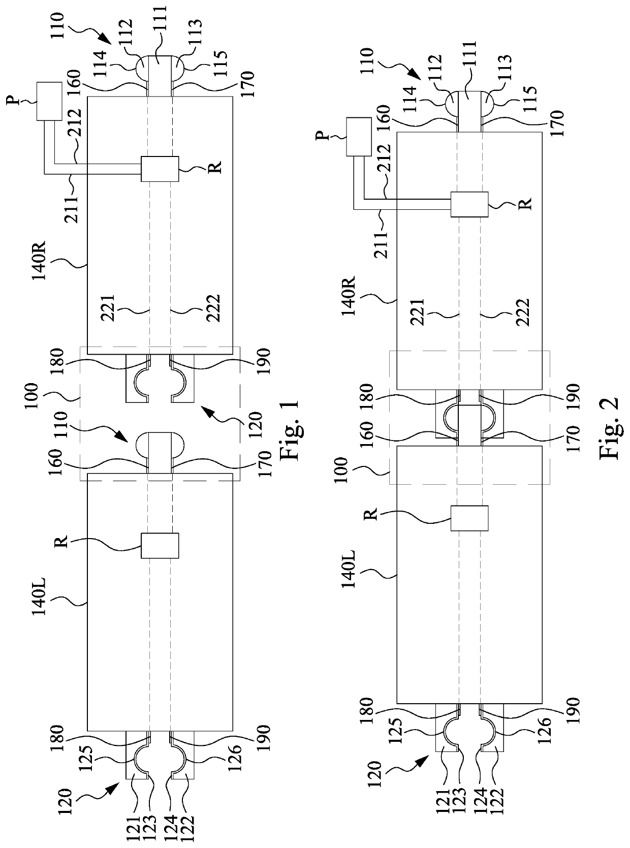
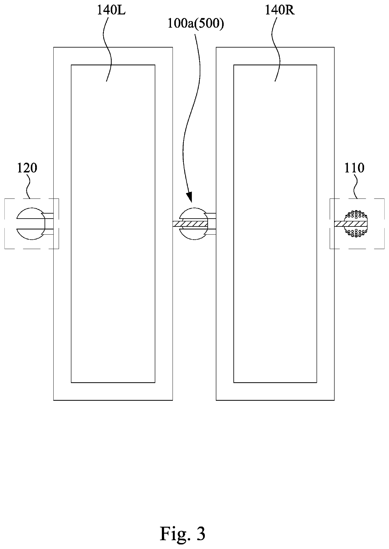
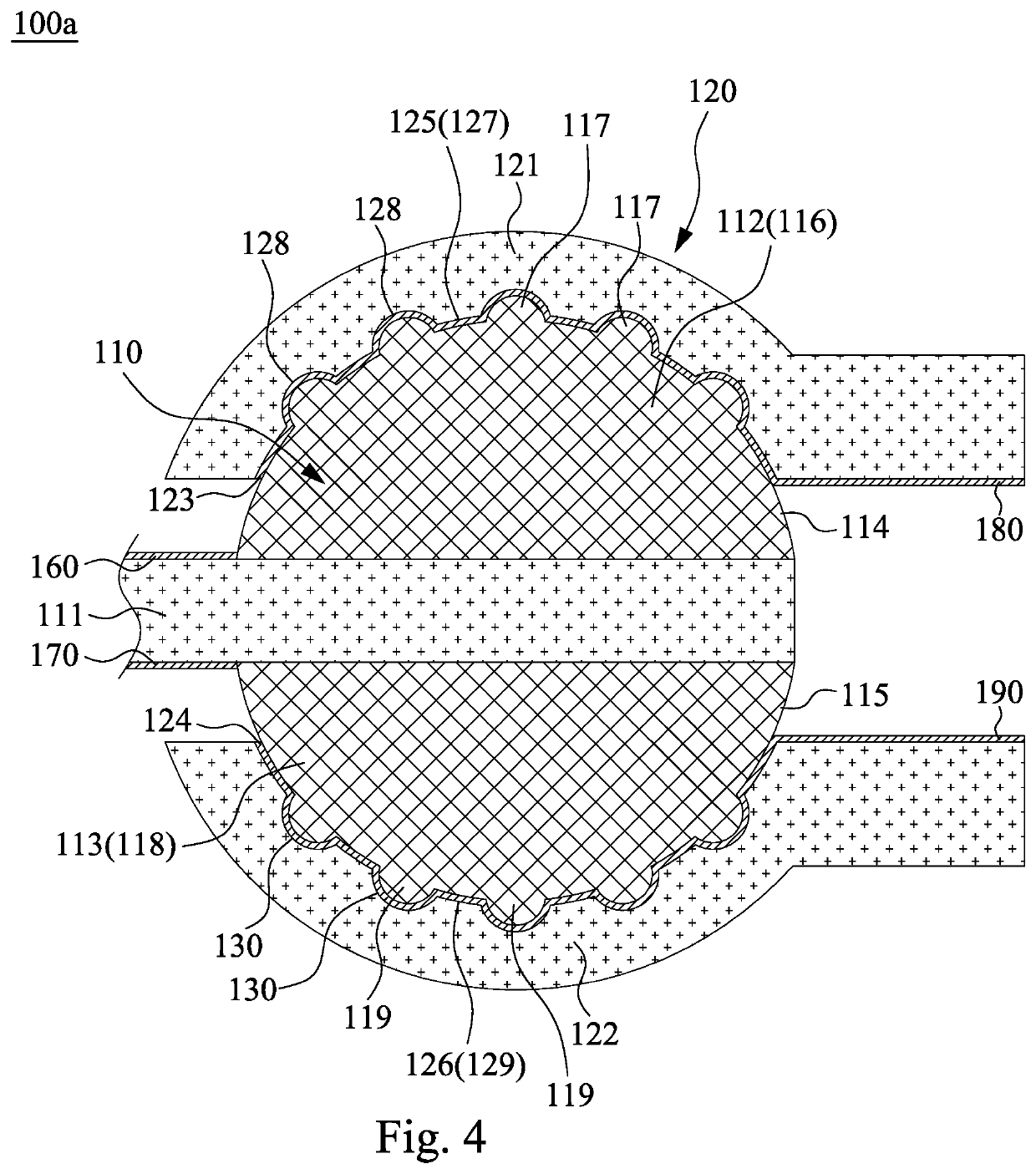
[0037]In view of the above, the first rounded body 116 and the first curved bumps 117 of the connector structure 100a in the second embodiment are configured to match the first rounded curved surface 127 and the first recesses 128, respectively. Moreover, the second rounded body 118 and the second curved bumps 119 are configured to match the second rounded curved surface 129 and the second recesses 130, respectively. The first and second curved bumps 117 and 119 and the first and second recesses 128 and 130 are configured to provide positioning points when the first connector 110 and the second connector 120 are relatively rotated. It should be particularly noted that the total number of the first curved bumps 117 and the second curved bumps 119 may not be equal to the total number of the first recesses 128 and the second recesses 130. For example, the total number of the first recesses 128 and the second recesses 130 may be greater than the total number of the first curved bumps 11...
third embodiment
[0040]FIG. 5 is a cross-sectional view of a connector structure 500 of the present disclosure. The connector structure 500 includes a core connector 510 and a housing connector 520. The core connector 510 includes a connector 511, a rounded insulating core body 512, a plurality of conductive bumps 513, and a plurality of first wires 514. The rounded insulating core body 512 is disposed at one end of the connector 511. Each of the conductive bumps 513 protrudes from the rounded insulating core body 512. The first wire 514 is substantially equipotentially connected to the conductive bump 513 from the connector 511 through the rounded insulating core body 512. Specifically, each of the first wires 514 is only connected to a single corresponding conductive bump 513. In some embodiments, the connector 511 and the rounded insulating core body 512 may include various polymeric materials such as polyurethane, acrylate, methacrylate, epoxy, polycarbonate, polyethylene, or polystyrene or othe...
fifth embodiment
[0049]In view of the above, the first rounded convex surface 625 and the first curved bumps 703 of the connector structure 600a in the fifth embodiment are configured to match the first rounded recess 614 and the first recesses 701, respectively. Moreover, the second rounded convex surface 626 and the second curved bumps 704 are configured to match the second rounded recess 615 and the second recesses 702, respectively. The first curved bumps 703 and the second curved bumps 704, and the first recesses 701 and the second recesses 702 are configured to provide positioning points when the first connector 610 and the second connector 620 are relatively rotated. It should be particularly noted that the total number of the first curved bumps 703 and the second curved bumps 704 may not be equal to the total number of the first recesses 701 and the second recesses 702. For example, the total number of the first recesses 701 and the second recesses 702 may be greater than the total number of...
PUM
 Abstract
Description
Claims
Application Information
 - R&D
- Intellectual Property
- Life Sciences
- Materials
- Tech Scout
- Unparalleled Data Quality
- Higher Quality Content
- 60% Fewer Hallucinations
Browse by: Latest US Patents, China's latest patents, Technical Efficacy Thesaurus, Application Domain, Technology Topic, Popular Technical Reports.
© 2025 PatSnap. All rights reserved.Legal|Privacy policy|Modern Slavery Act Transparency Statement|Sitemap|About US| Contact US: help@patsnap.com


