
Method to enhance operation efficiency of water turbines and to reduce cavitation of components thereof

Active Publication Date: 2020-05-07
LIN ZUEI LING
View PDF0 Cites 4 Cited by
  • Summary
  • Abstract
  • Description
  • Claims
  • Application Information

AI Technical Summary

Benefits of technology

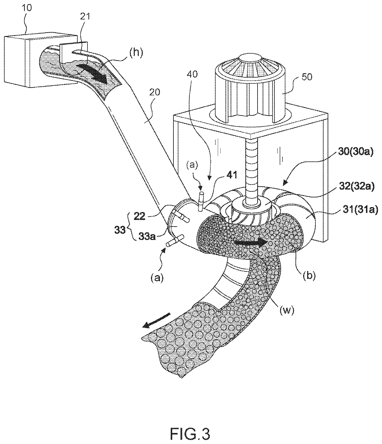
The present invention provides a method for improving the power generation efficiency of a water turbine while preventing cavitation of its components. This is achieved by disposing an air guiding device between the penstock and the plurality of runner blades, which guides external air into the water flow and creates a negative pressure at the outlet of the device to produce a plurality of pressured air bubbles. These bubbles then mix with the water flow to enhance the operation efficiency of the water turbine and reduce damage caused by cavitation.

Problems solved by technology

However, there is a special physical phenomenon in the operation of the turbine, that is, the high-speed water flow in the turbine to the guide plate, the impeller and other related parts and accessories, the impact produces high-pressure zone and low-pressure zone, and the potential energy conversion of water in the high-pressure zone for electric energy, when the pressure in the low pressure zone is lower than the vapor pressure of water, the water vaporizes and generates air bubbles, which causes erosion of the components of the turbine, thus affecting the efficiency and service life of the water turbine.
However, in order to prevent cavitation of water turbine-related parts and accessories, only special metal materials resistant to cavitation can be used, but they are expensive and difficult to process, such as special stainless steel materials such as ASTM A487 stainless steel.
Hence, if the design is too complicated to improve the above problems, or the design of the structure of the turbine will be changed, it is not easy to complete, and it is costly.

Method used


Image

  • Method to enhance operation efficiency of water turbines and to reduce cavitation of components thereof
  • Method to enhance operation efficiency of water turbines and to reduce cavitation of components thereof
  • Method to enhance operation efficiency of water turbines and to reduce cavitation of components thereof

Examples


Embodiment Construction

[0032]The following provides a preferred embodiment of the technical features of the present invention; however, there are many types of water turbines, and the shapes and structures are not completely the same. Therefore, although only the preferred embodiment is described, the technical means used thereof are the same, so they are not described one by one. The water turbine parts and accessories described below include related components such as water turbine parts and accessories. Another runner blade may also be referred to as an impeller.

[0033]Please referring to an embodiment in the following with reference to FIGS. 3-10. A method to enhance operation efficiency of water turbines and to reduce cavitation of components thereof, comprising: having a penstock 20 installed on a dam 10 at a hydroelectric power station, said penstock having an entry 21 at an upper end and an exit 22 at a lower end; having a water turbine 30 with a casing 31 and a plurality of runner blades 32 dispos...


PUM


Abstract

A method to dispose at least one air guiding tube between a penstock and a water turbine installed on a dam to form negative pressure at an outlet of the air guiding device by the water kinetic energy produced from high speed of water flow to take in external air for pressurizing, so as to produce a plurality of pressured air bubbles mixed into the water. The water with pressured air bubbles would be decompressed when flowing to an exit of the penstock and has their volumes increased, so as to enhance the water kinetic energy for driving the water turbine more efficiently; meanwhile the method can prevent from production of cavities and further avoid damages of the components of the water turbine from cavitation.

Description

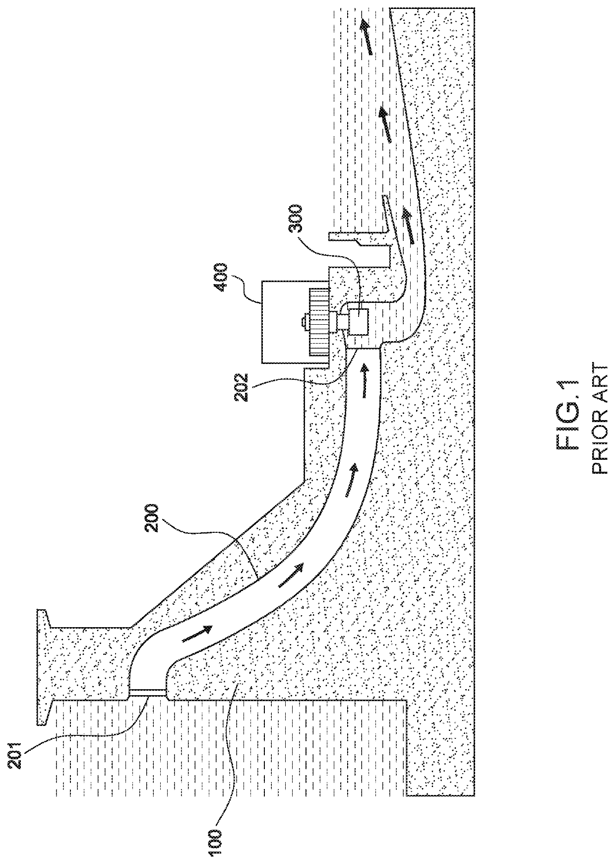
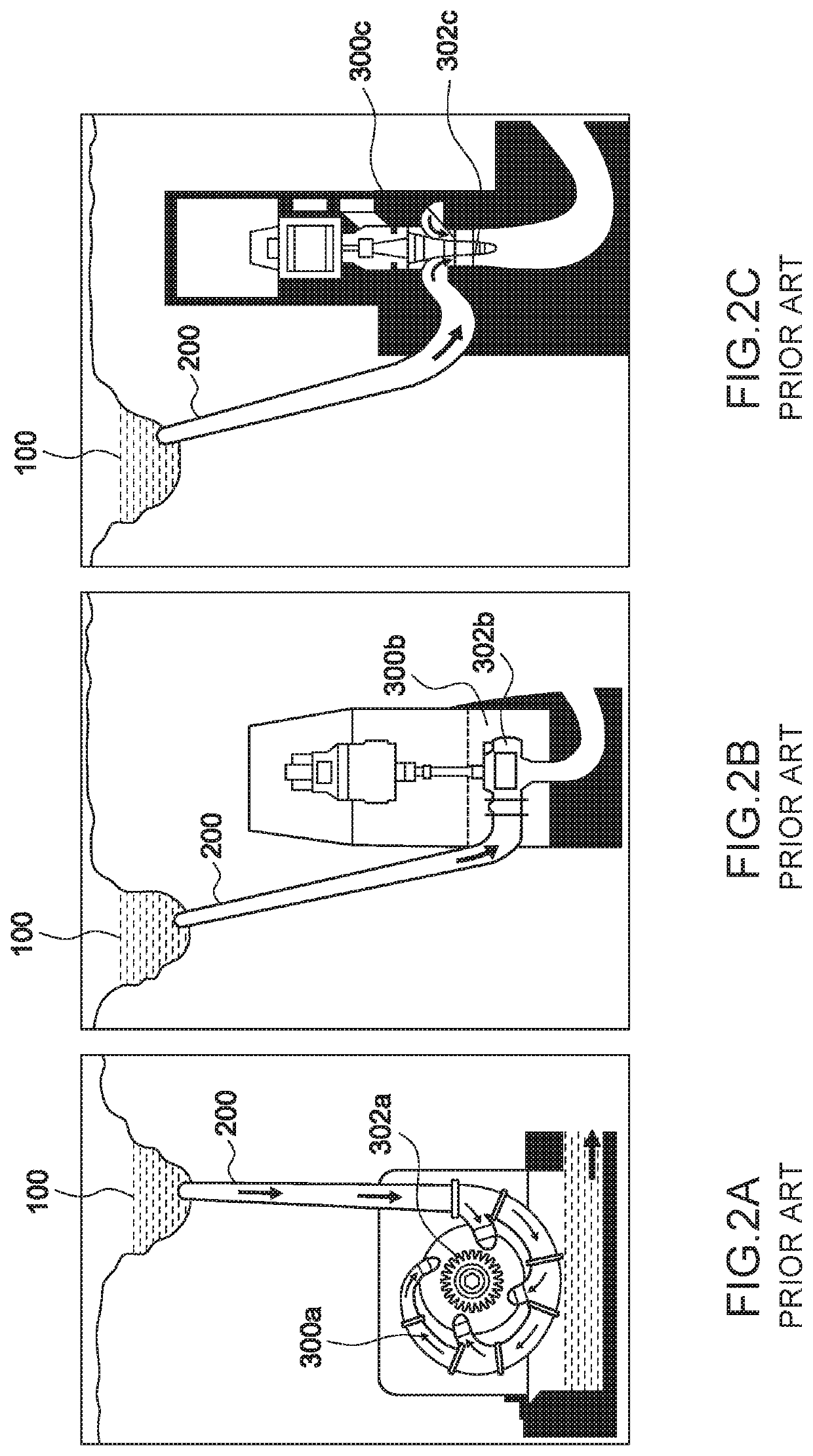
BACKGROUND OF THE INVENTION1. Field of Invention[0001]The present invention relates to a method to enhance operation efficiency of water turbines and to reduce cavitation of components thereof.2. Description of the Related Art[0002]As shown in FIG. 1, a water turbine 300 has a penstock 200 installed on a dam 100 at a hydroelectric power station and the penstock has an entry 201 and an exit 202 for the water to flow through the entry 201 of the water penstock 200 from the top to the bottom of the exit 202 to the water turbine 300, and the water turbine 300 rotates and drives a generator 400 connected thereto to generate electrical energy.[0003]The water turbine can be roughly classified into an impulse turbine and a reaction turbine according to its working principle. Among them, the impulse turbine uses a high-speed water flow impacting runner blade or water bucket 302a for work, and the main representative model is a Pelton Turbine 300a as shown in FIG. 2A. As for the reaction turb...

Claims


Application Information

Patent Timeline
IPC IPC(8): F03B15/08F03B13/10F03B11/00
CPCF03B15/08F03B11/004F03B13/10F03B11/002F03B11/04F05B2260/64F03B13/08F03B3/02F05B2210/18Y02E10/20Y02P70/50
Inventor LIN, ZUEI-LING
Owner LIN ZUEI LING
Learn More