Cutting apparatus

a cutting apparatus and cutting technology, applied in cutting machines, mining structures, slitting machines, etc., can solve the problems of large force on cutters, cutters that conventional cutting machines are not optimised for cutting hard rock having a strength, etc., to achieve optimised cutting geometry, reduce the occurrence of pulling side forces, and optimise the effect of geometry

Active Publication Date: 2020-05-07
SANDVIK INTELLECTUAL PROPERTY AB
View PDF0 Cites 1 Cited by
  • Summary
  • Abstract
  • Description
  • Claims
  • Application Information

AI Technical Summary

Benefits of technology

[0008]It is an objective of the present invention to provide cutting apparatus suitable to form tunnels and subterranean roadways being specifically configured to cut hard rock, say beyond 120 MPa, in a controlled and reliable manner, that is, apparatus capable of mine development work. It is a further objective to provide a cutting apparatus capable of creating a tunnel with a variable cross sectional area within a maximum and a minimum cutting range. It is a further objective to provide cutting (excavator) apparatus operable in an ‘undercutting’ mode according to a two stage cutting action. It is a further objective to provide a cutter that has an optimised cutting geometry for the cutting apparatus. It is a further objective to provide a cutter that reduces the occurrence of pulling side forces. It is a further object to provide a cutter that has an optimised geometry for balancing cutter strength and reducing cutter wear.

Problems solved by technology

However, conventional cutting machines are not optimised to cut hard rock having a strength typically beyond 120 MPa whilst creating a tunnel or subterranean cavity safely and reliably of desired cross sectional configuration.
WO2016 / 055087 describes a type of machine that addresses some of these problems, however the inventors have determined that the cutters used on that machine are not as well optimised for the cutting apparatus as they could be.
A further issue with known cutting machines is that the cutters experience large forces during a cutting operation.
It is the relatively high frequency of change of direction of the side force transmitted to the bearings that shortens the life of the bearings.

Method used


Image

  • Cutting apparatus
  • Cutting apparatus
  • Cutting apparatus

Examples


Embodiment Construction

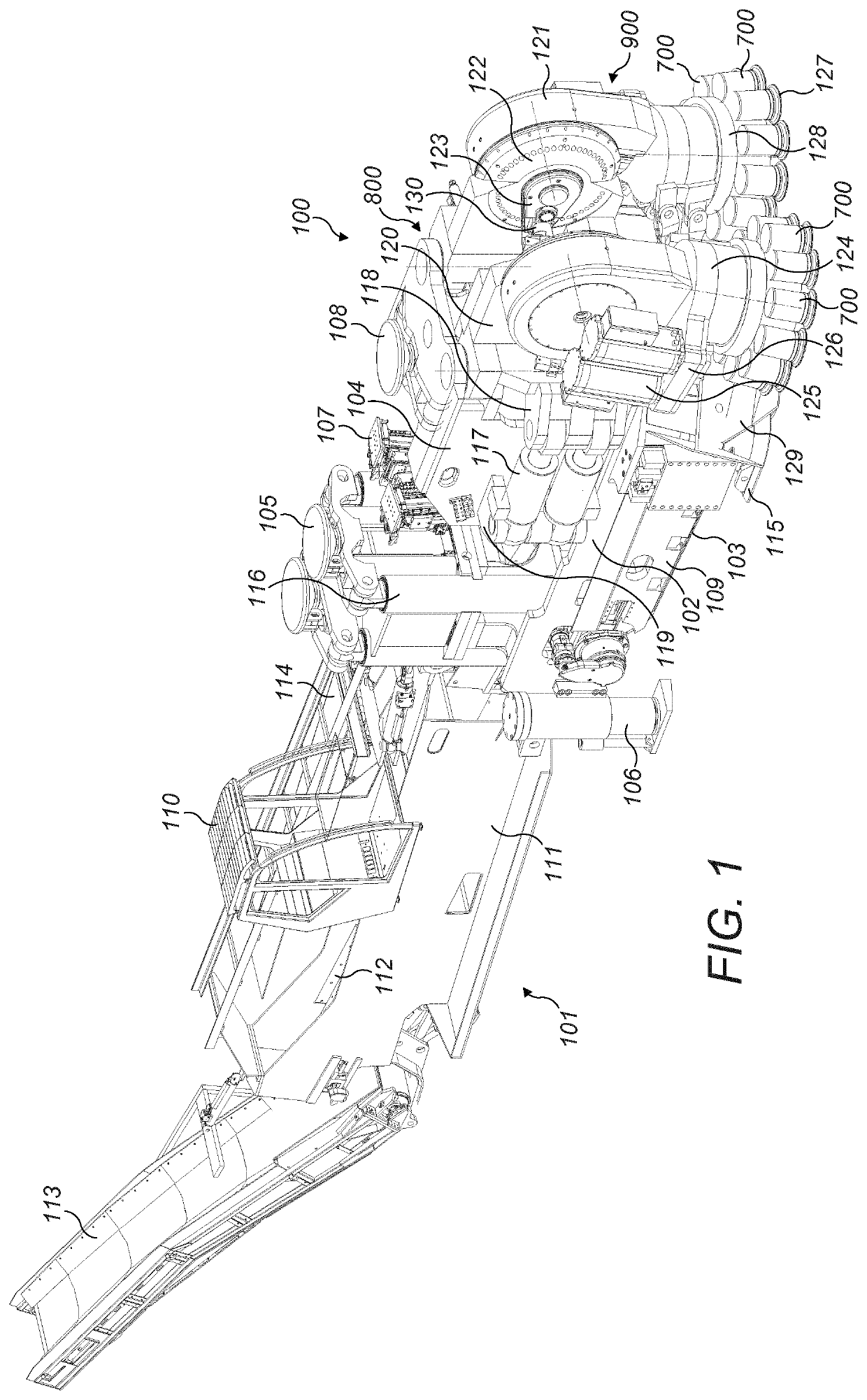
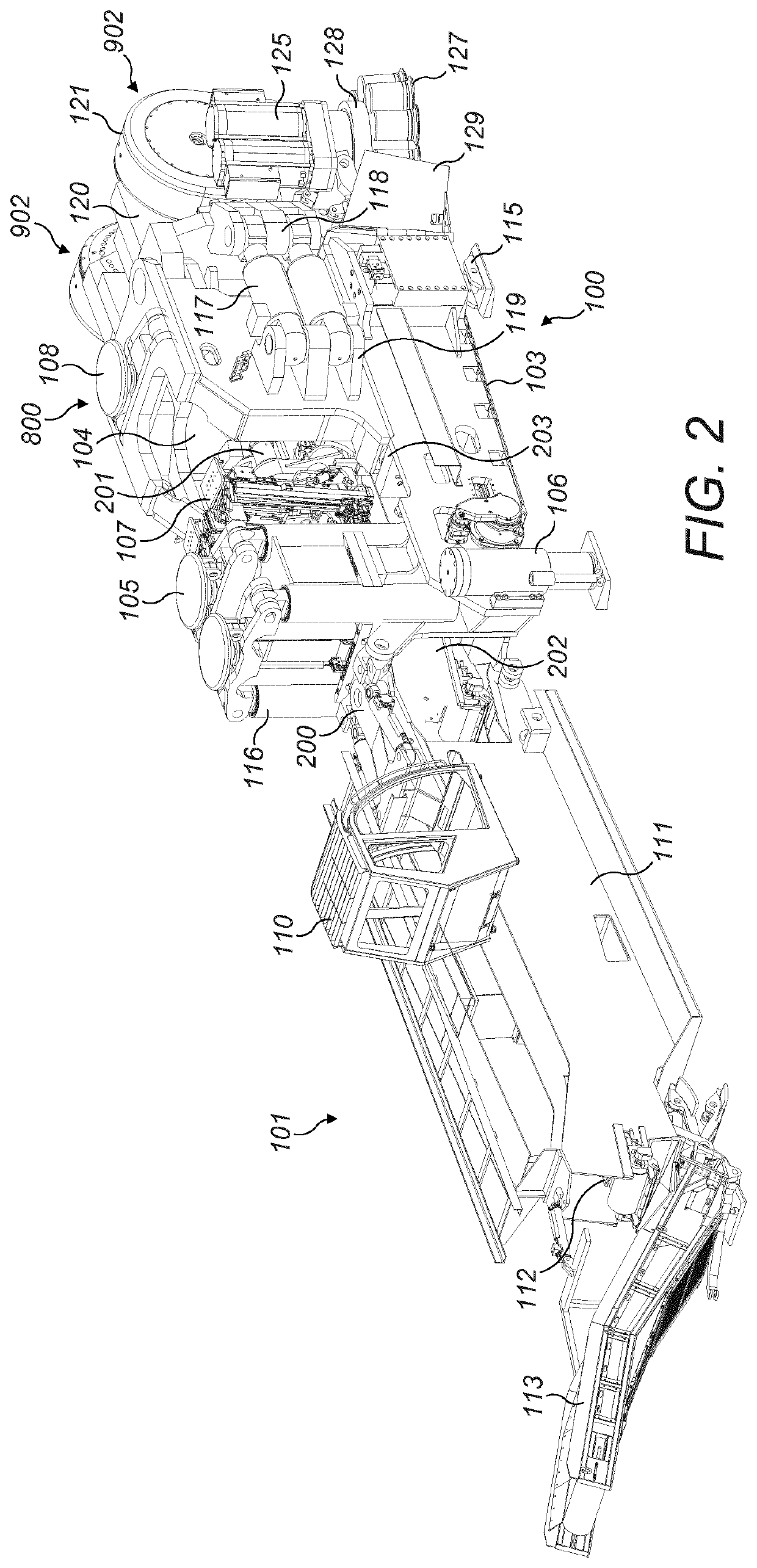
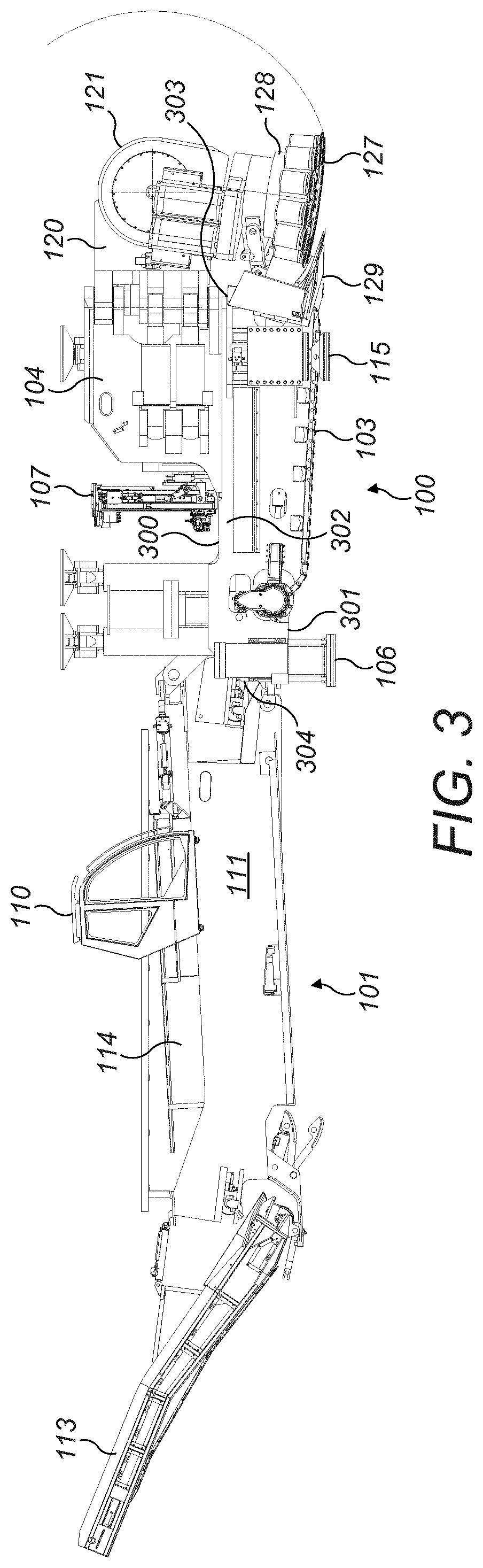
[0070]Referring to FIGS. 1 to 7, cutting apparatus 100 comprises a support structure 800 mounting a plurality of cutting components configured to cut into a rock or mineral face 1000 to create tunnels or subterranean roadways. Apparatus 100 is configured specifically for operation in an undercutting mode in which a plurality of rotatable roller cutters 127 may be forced into the rock to create a groove or channel and then to be pivoted vertically upward so as to overcome the reduced tensile force immediately above the groove or channel and break the rock. Accordingly, the present cutting apparatus is optimised for forward advancement into the rock or mineral utilising less force and energy typically required for conventional compression type cutters that utilise cutting bits or picks mounted at rotatable heads. However, the present apparatus may be configured with different types of cutting head to those described herein including in particular pick or bit type cutting heads in whic...


PUM


Abstract

A cutter for a cutting unit used in cutting apparatus suitable for creating tunnels or subterranean roadways. The cutter includes a disc body having an underside, an upper side arranged substantially opposite to the underside, and a radially peripheral part. A plurality of buttons for abrading rock are mounted in the radially peripheral part of the disc body and protrude outwardly therefrom to engage rock during an undercutting operation, wherein at least some of the buttons have a cutting part having a dome-shaped cutting surface.

Description

FIELD OF INVENTION[0001]The present invention relates to rock cutting apparatus suitable for creating tunnels or subterranean roadways and in particular, although not exclusively, to undercutting apparatus in which a plurality of rotating heads are capable of being slewed laterally outward and raised in the upward and downward direction during forward cutting. The apparatus is particularly suited to development mining. The present invention also relates to a cutter for a cutting unit used in the cutting apparatus.[0002]Background art[0003]A variety of different types of excavation machines have been developed for cutting drifts, tunnels, subterranean roadways and the like in which a rotatable head is mounted on an arm that is in turn movably mounted at a main frame so as to create a desired tunnel cross sectional profile. WO2012 / 156841, WO 2012 / 156842, WO 2010 / 050872, WO 2012 / 156884, WO2011 / 093777, DE 20 2111 050 143 U1 all described apparatus for mill cutting of rock and minerals i...

Claims


Application Information

Patent Timeline
Patent Type & Authority Applications(United States)
IPC IPC(8): E21D9/10E21D9/11
CPCE21D9/117E21D9/104E21C25/16E21D9/102E21C25/18E21C27/24E21D9/10E21D9/11E21B10/12E21D9/1006E21D9/1026
Inventor GARCIA, LUISSTABER, GUENTHER
Owner SANDVIK INTELLECTUAL PROPERTY AB
Why Eureka
Try Eureka