
Stacked connector

Active Publication Date: 2020-04-30
SUMITOMO WIRING SYST LTD
View PDF11 Cites 1 Cited by
  • Summary
  • Abstract
  • Description
  • Claims
  • Application Information

AI Technical Summary

Benefits of technology

The present invention relates to a connector assembly that can detect when a terminal fitting is only partly inserted, which can cause damage or malfunction. The technical effects of this invention include preventing deformation of the housing due to interference from the detecting portion, and improving the reliability of detecting incomplete insertion of the terminal fitting by making it more difficult for the connector to be inserted into a tool.

Problems solved by technology

However, the detecting portion may receive an excessive reaction force from an incompletely inserted terminal fitting and may be squeezed.
Consequently, the incompletely inserted state of the terminal fitting may not be detected.

Method used


Image

  • Stacked connector
  • Stacked connector
  • Stacked connector

Examples


Embodiment Construction

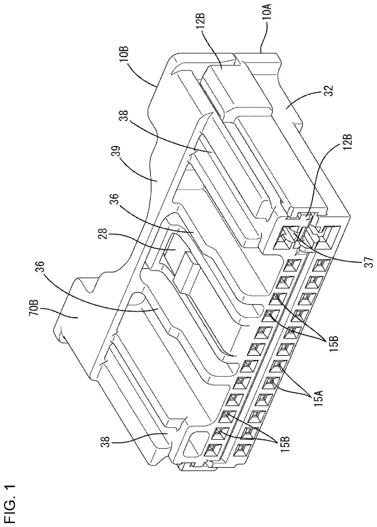
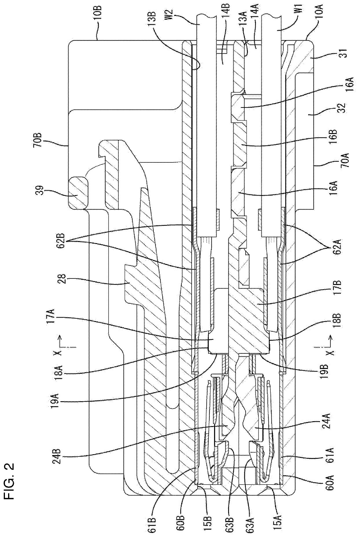
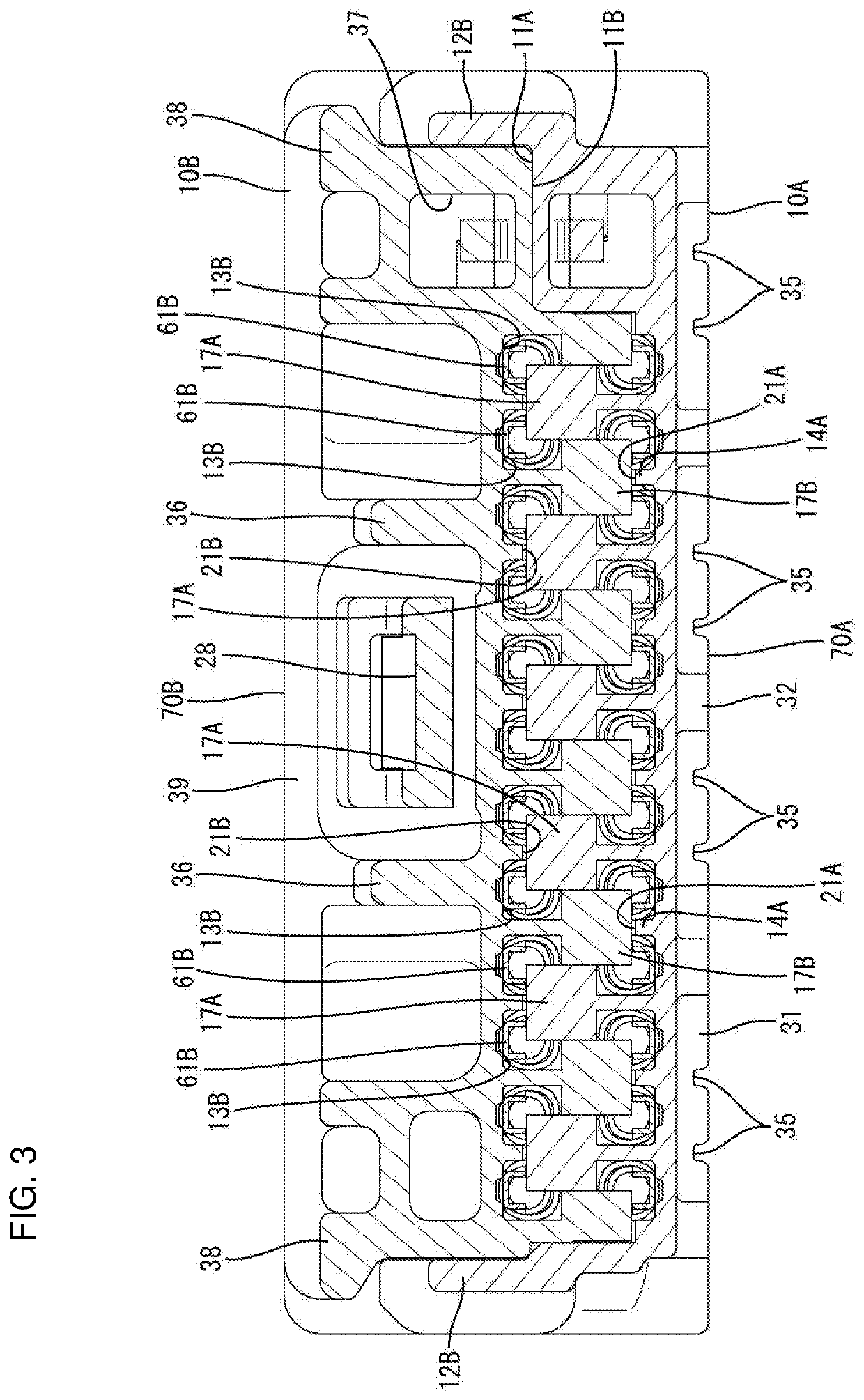
[0020]An embodiment is described with reference to FIGS. 1 to 9. A stacked connector of this embodiment includes a first housing 10A and a second housing 10B to be stacked one on the other. First terminal fittings 60A and second terminal fittings 60B are to be accommodated respectively into the first and second housings 10A, 10B. In the following description, a left side of FIGS. 2 and 4 is referred to as a front concerning a front-rear direction and a vertical direction is based on a vertical direction of the figures except FIG. 7.

[0021]The first housing 10A is a lower housing and, as shown in FIG. 6, has a flat shape with a width direction intersecting a vertical direction (stacking direction) as a longitudinal direction and has a first facing surface 11A facing the second housing 10B as a stacking partner on an upper surface. The first housing 10A includes first housing locks 12A in the form of plates extending along the front-rear direction on both widthwise sides.

[0022]The firs...


PUM


Abstract

A stacked connector includes a first housing (10A) and a second housing (10B) to be stacked one on the other. The first and second housings (10A, 10B) respectively include first detecting portions (17A) and second detecting portions (17B) configured to interfere with incompletely inserted second terminal fittings (60B) and first terminal fittings (60A) on a first facing surface (11A) and a second facing surface (11B). The first housing (10A) is recessed with groove portions (35) formed in an outer side surface opposite to the first facing surface (11A) by cutting a region along a width direction, extending in a depth direction, and open on both ends in the depth direction.

Description

BACKGROUNDField of the Invention[0001]The invention relates to a stacked connector.Related Art[0002]Japanese Unexamined Patent Publication No. 2006-294580 discloses a connector with two housings to be stacked on and united with each other. Connector housing locking means are disposed on both end parts in a width direction intersecting a stacking direction and are configured for holding the connector housings in a united state. Detecting portions project from a facing surface of one connector housing facing a facing surface of the other connector housing and interfere with terminal fittings accommodated in the other connector housing to detect an incompletely inserted state of the terminal fittings.[0003]Interference of the detecting portion of the one connector housing with the incompletely inserted terminal fitting restricts the entrance of the detecting portion into the other connector housing. Thus, a clearance is formed between the facing surfaces of the connector housings at a ...

Claims


Application Information

Patent Timeline
IPC IPC(8): H01R13/506H01R13/424H01R43/20H01R24/20
CPCH01R13/506H01R24/20H01R43/20H01R13/424H01R2107/00H01R13/514H01R13/4361H01R13/4223
Inventor TSUKIYOSHI, KEIICHIHARADA, YUTO
Owner SUMITOMO WIRING SYST LTD
Learn More