Elevatable supporting device
a technology of supporting device and bending surface, which is applied in the direction of machine supporting, mechanical equipment, stand/trestle, etc., can solve the problems of shorter life of energy storage element, higher accuracy requirements of curved surface of cam, and conventional supporting devi
- Summary
- Abstract
- Description
- Claims
- Application Information
AI Technical Summary
Benefits of technology
Problems solved by technology
Method used
Image
Examples
first embodiment
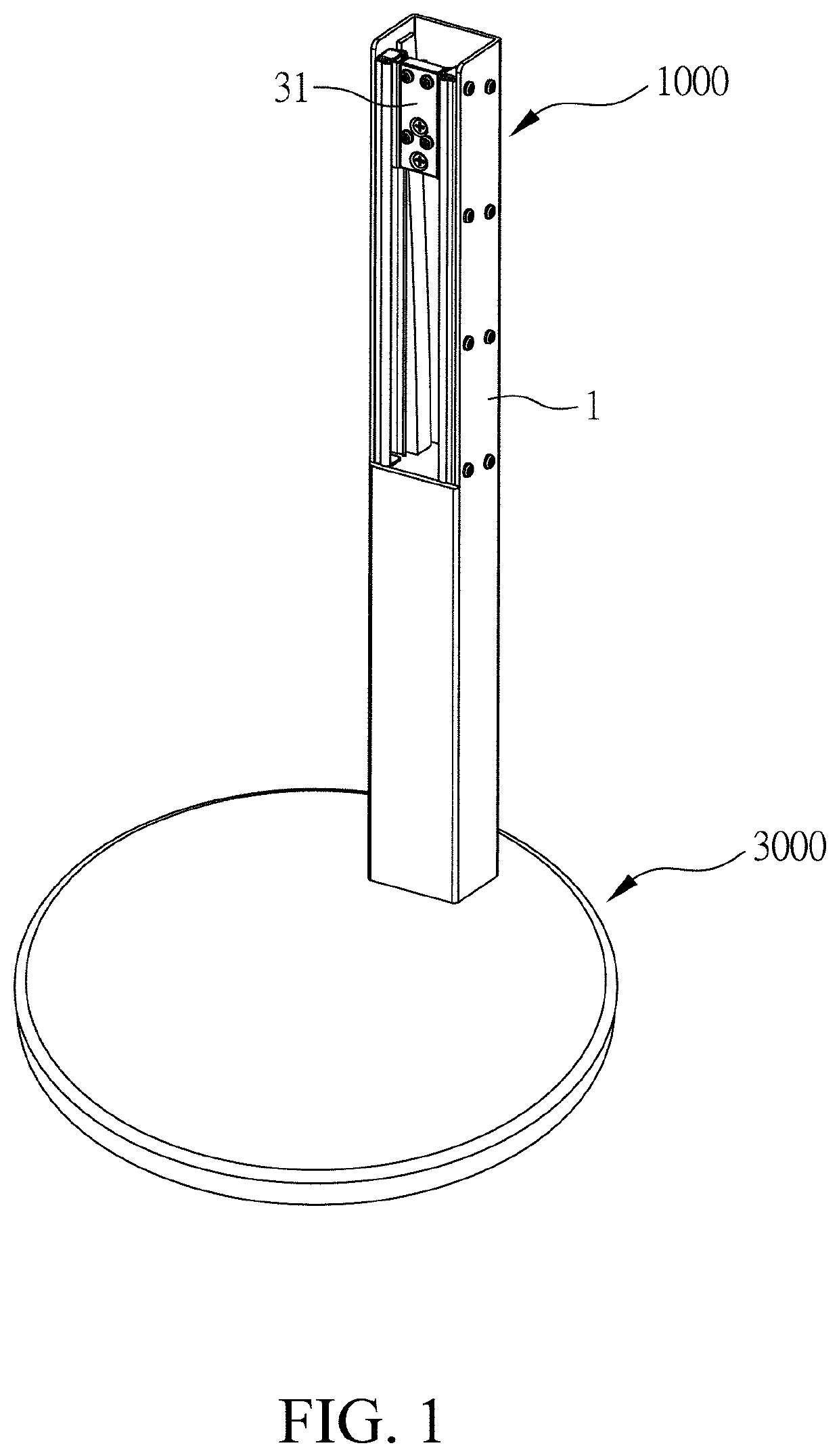
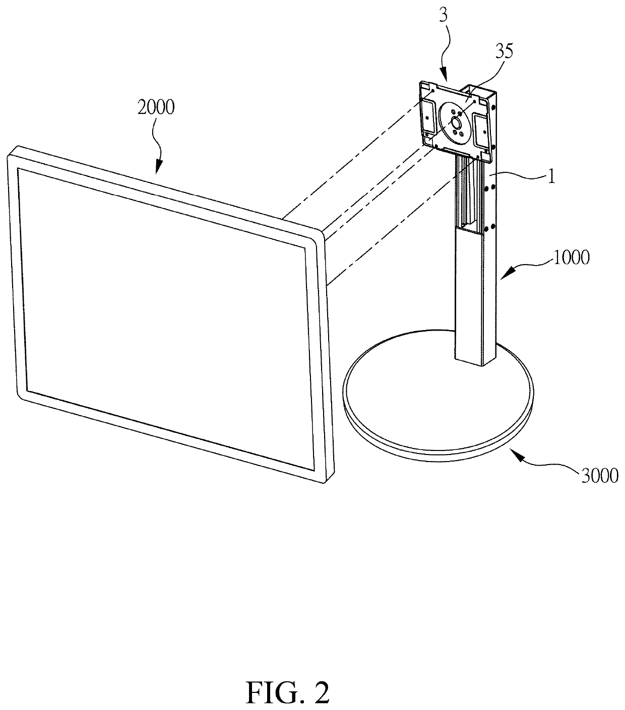
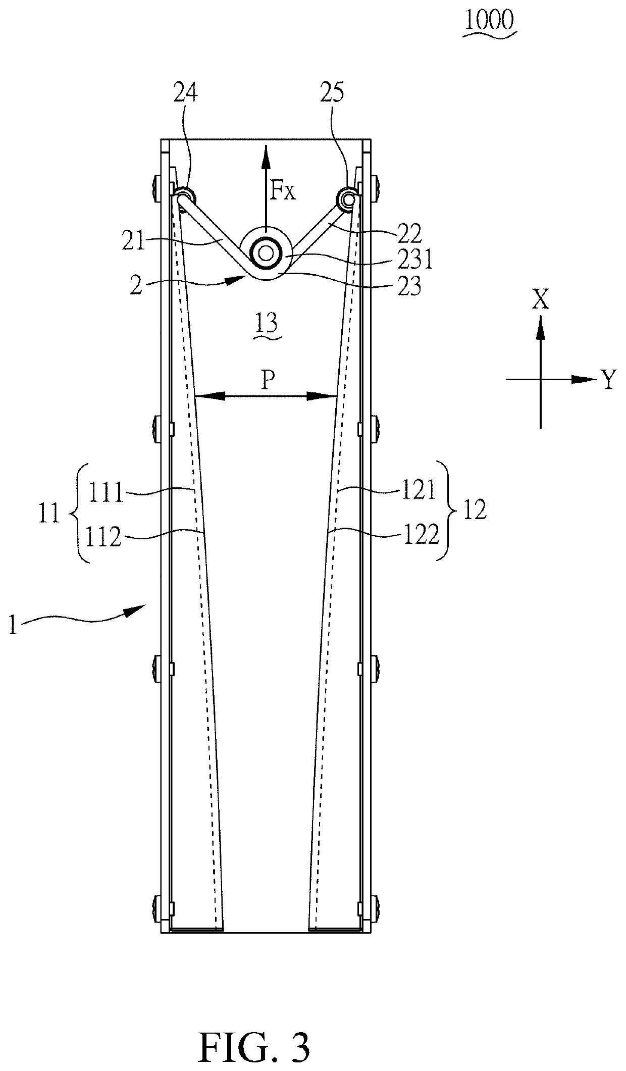
[0040]Please refer to FIG. 3 and FIG. 4, which illustrate a partial view and a top view of the elevatable supporting device 1000 of the present invention. The elevatable supporting device 1000 comprises an upright 1, an energy storage element 2, and a bearing module 3. The upright 1 extends along a first axis X and including a first surface 11, a second surface 12 being non-parallel to the first surface 11, and an accommodating space 13 formed between the first surface 11 and the second surface 12. In the present embodiment, the upright 1 further includes a sliding module 14 disposed along the first axis X and being adjacent to the first surface 11 and the second surface 12. As illustrated in FIG. 4, the sliding module 14 includes two slide rails; therefore, the bearing module 3 can be slidably connected to the slide rails and slides back and forth along the first axis X with respect to the upright 1.
[0041]Furthermore, the energy storage element 2 is disposed in the accommodating sp...
second embodiment
[0056]Please refer to FIG. 6 and FIG. 7 illustrating the partial perspective view and the top view of the elevatable supporting device 1000 of the present invention.
[0057]The operation principle of the present embodiment is similar to that of the first embodiment, the difference between them is that the energy storage element 2 includes a V-shaped elastic steel plate. The V-shaped elastic steel plate is preferably made of a flat spring, wherein the connecting section 23 having a pre-opening angle is formed by bending the elastic plate. Different from the torsional spring utilized in the first embodiment, the connecting section 23 of the energy storage element 2 does not include a winding portion 231, so that the energy storage element 2 and the bearing module 3 are not actuated together through the winding portion 231 that set on the shaft 32. As illustrated in FIG. 8, the bearing module 3 of the present embodiment has two shafts 32, a block 33, a screw 36, and a nut 37. The block 3...
third embodiment
[0059]Please refer to FIG. 9 and FIG. 10, which illustrate the rear partial perspective view and the top view of the elevatable supporting device 1000 of the present invention.
[0060]The structural features are similar to that of the second embodiment, wherein the energy storage element 2 comprises a V-shaped elastic steel plate with a pre-opening angle, a first follower 24 and the second follower 25 are actuated together with the first arm 21 and the second arm 22 through the first pivotal unit 26 and the second pivotal unit 27 to which the first follower 24 and the second follower 25 are pivotally fixed. The difference between the present embodiment and the second embodiment is that the present embodiment does not comprise the block 33 in the second embodiment. The bearing module 3 is actuated together with the energy storage element 2 by directly clamping two sides of the connecting section 23 with the shaft 32.
PUM
 Abstract
Description
Claims
Application Information
 - R&D
- Intellectual Property
- Life Sciences
- Materials
- Tech Scout
- Unparalleled Data Quality
- Higher Quality Content
- 60% Fewer Hallucinations
Browse by: Latest US Patents, China's latest patents, Technical Efficacy Thesaurus, Application Domain, Technology Topic, Popular Technical Reports.
© 2025 PatSnap. All rights reserved.Legal|Privacy policy|Modern Slavery Act Transparency Statement|Sitemap|About US| Contact US: help@patsnap.com


