
Detachment puller

Active Publication Date: 2020-04-30
BO CHEN HUNG CO LTD
View PDF4 Cites 2 Cited by
  • Summary
  • Abstract
  • Description
  • Claims
  • Application Information

AI Technical Summary

Benefits of technology

The patent is about a detachment puller that provides quick and stable operation using bi-directional forces. The technical effect of the invention is that it allows for more efficient and effective detachment of parts.

Problems solved by technology

However, in the prior art, each said engaging portion abuts against the toothed face of each said jaw to fix a pivoting angle of each said jaw, a user has to swing the plurality of jaws to appropriate positions one by one through an exterior force (for example, hands), so it is inconvenient and complicated to operate.

Method used


Image

  • Detachment puller
  • Detachment puller
  • Detachment puller

Examples


Embodiment Construction

[0019]The present invention will be clearer from the following description when viewed together with the accompanying drawings, which show, for purpose of illustrations only, the preferred embodiment in accordance with the present invention.

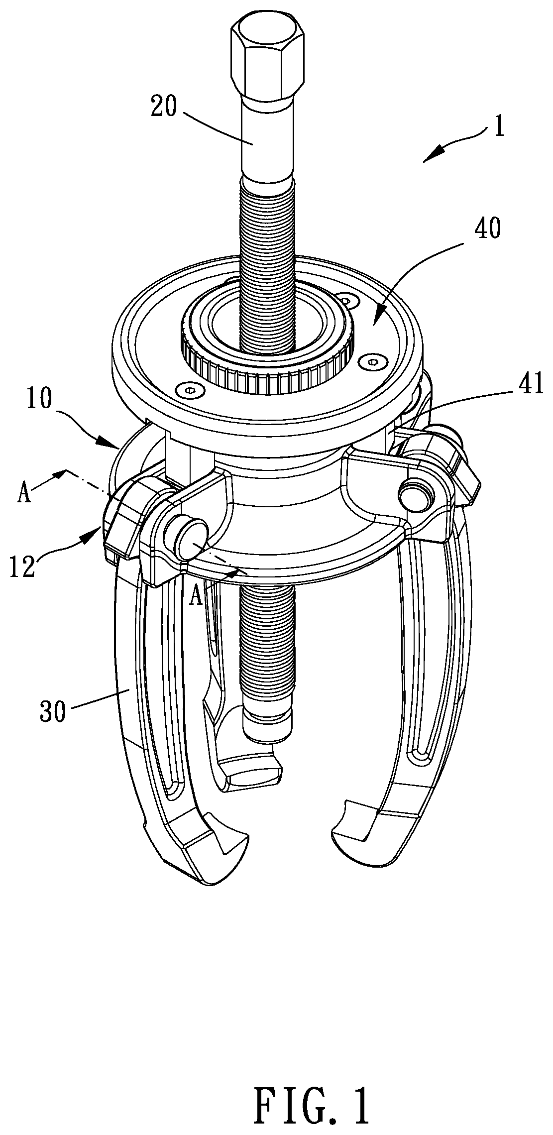
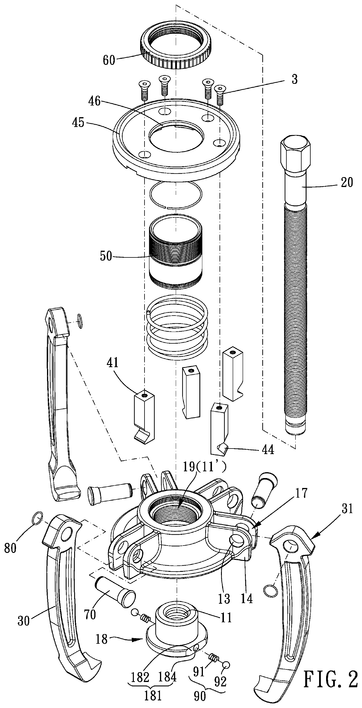
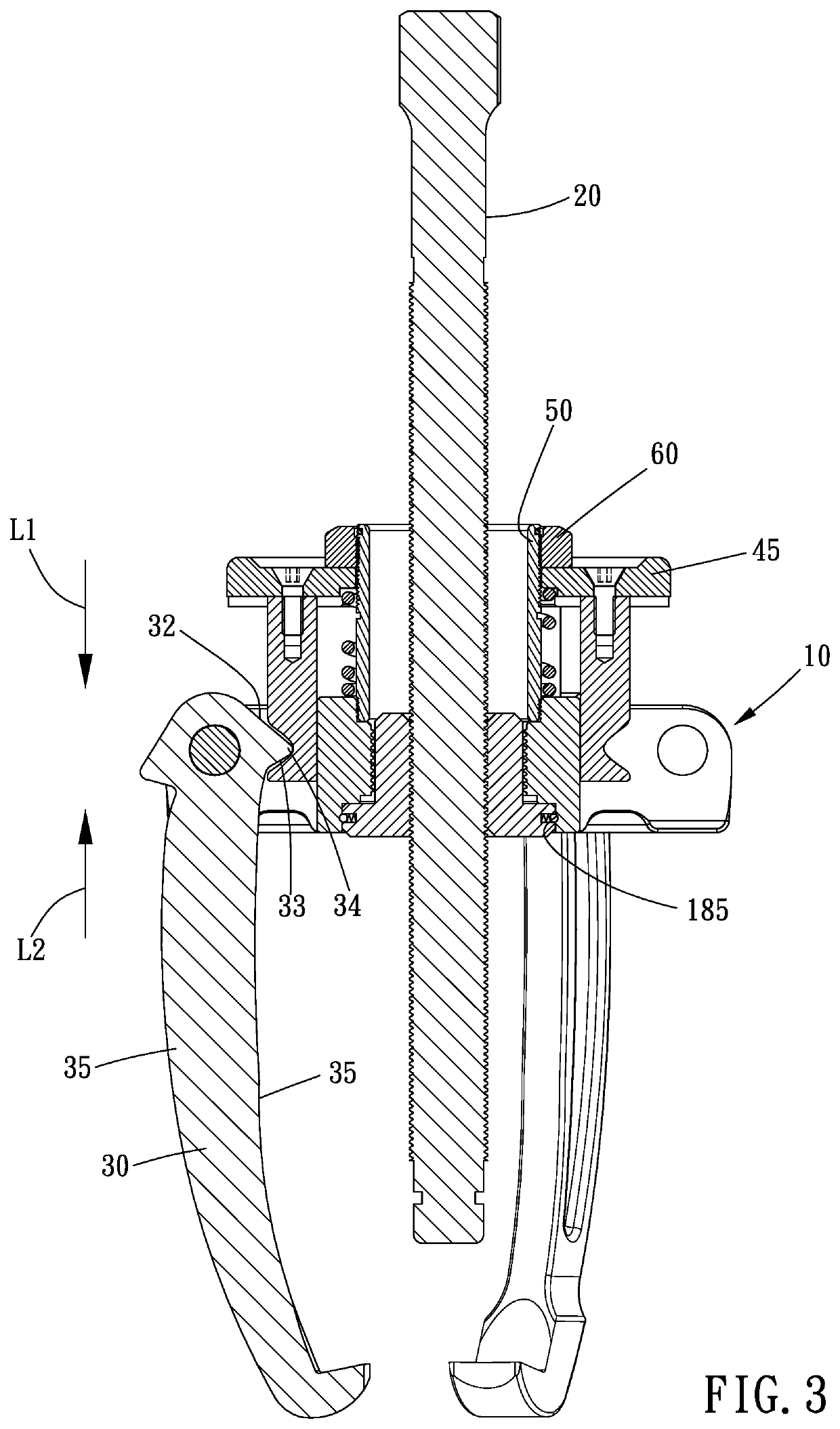
[0020]Please refer to FIGS. 1 to 9 for a preferred embodiment of the present invention. A detachment puller 1 includes a main body 10, a screw rod 20, a plurality of jaw 30 and an adjustment mechanism 40.

[0021]The main body 10 has a threaded hole 11 and a plurality of pivoting portions 12 circumferentially disposed around the threaded hole 11; the screw rod 20 is screwed with the threaded hole 11; the plurality of jaws 30 are respectively pivoted to the plurality of pivoting portions 12, and each of the plurality of jaws 30 includes an abutted portion 31; the adjustment mechanism 40 is elastically and movably disposed on the main body 10, the adjustment mechanism 40 includes a plurality of engaging portions 41, each of the plurality of engaging p...


PUM


Abstract

A detachment puller is provided, including a main body, having a threaded hole and a plurality of pivoting portions circumferentially disposed around the threaded hole; a screw rod, screwed with the threaded hole; a plurality of jaws, respectively pivoted to the plurality of pivoting portions, each of the plurality of jaws including an abutted portion; an adjustment mechanism, elastically and movably disposed on the main body, the adjustment mechanism including a plurality of engaging portions, each of the plurality of engaging portions including a first abutting portion and a second abutting portion, the abutted portion being located between the first and second abutting portions, the first abutting portion being movable toward a first direction to press the abutted portion, the second abutting portion being movable toward a second direction to press the abutted portion, the first and second directions being opposite to each other.

Description

BACKGROUND OF THE INVENTIONField of the Invention[0001]The present invention relates to a detachment puller.Description of the Prior Art[0002]As disclosed in TWM518284, the prior art includes a main body, an upper cover and a plurality of jaws, the main body has a plurality of engaging grooves which are open laterally; the upper cover is fixed on the main body, and the upper cover has a plurality of engaging portions; the plurality of jaws are respectively pivoted to each of the plurality of engaging grooves, and each of the plurality of jaws has a toothed face which corresponds to the engaging portion.[0003]However, in the prior art, each said engaging portion abuts against the toothed face of each said jaw to fix a pivoting angle of each said jaw, a user has to swing the plurality of jaws to appropriate positions one by one through an exterior force (for example, hands), so it is inconvenient and complicated to operate.[0004]The present invention has arisen to mitigate and / or obvi...

Claims


Application Information

Patent Timeline
IPC IPC(8): B25B5/10B23P19/04
CPCB25B5/10B23P19/04B25B27/023B25B27/062
Inventor WANG, MING-YU
Owner BO CHEN HUNG CO LTD
Learn More