
Ignition system having a high-frequency plasma-enhanced ignition spark of a spark plug, including an antechamber, and a method associated therewith

a high-frequency plasma-enhanced, spark-plug technology, applied in the direction of spark-plugs, machines/engines, mechanical equipment, etc., can solve the problems of fuel-air mixture misfiring and/or incomplete combustion

Active Publication Date: 2020-04-16
VOLKSWAGEN AG +1
View PDF0 Cites 0 Cited by
  • Summary
  • Abstract
  • Description
  • Claims
  • Application Information

AI Technical Summary

Benefits of technology

The patent aims to improve the reliability and complete combustion of fuel-air mixtures, even under adverse conditions. This allows for higher dilution rates and further reduction in fuel consumption. One way to achieve this is by lessening the known ignition problem of prechamber spark plugs without the need for high-frequency plasma assistance.

Problems solved by technology

In the case of mixtures having a high level of excess air (lean mixture) and / or mixtures diluted by exhaust gas recirculation, flammability problems can occur and thereby result in incomplete combustion and / or misfirings of the fuel-air mixture.

Method used


Image

  • Ignition system having a high-frequency plasma-enhanced ignition spark of a spark plug, including an antechamber, and a method associated therewith
  • Ignition system having a high-frequency plasma-enhanced ignition spark of a spark plug, including an antechamber, and a method associated therewith
  • Ignition system having a high-frequency plasma-enhanced ignition spark of a spark plug, including an antechamber, and a method associated therewith

Examples


first specific embodiment

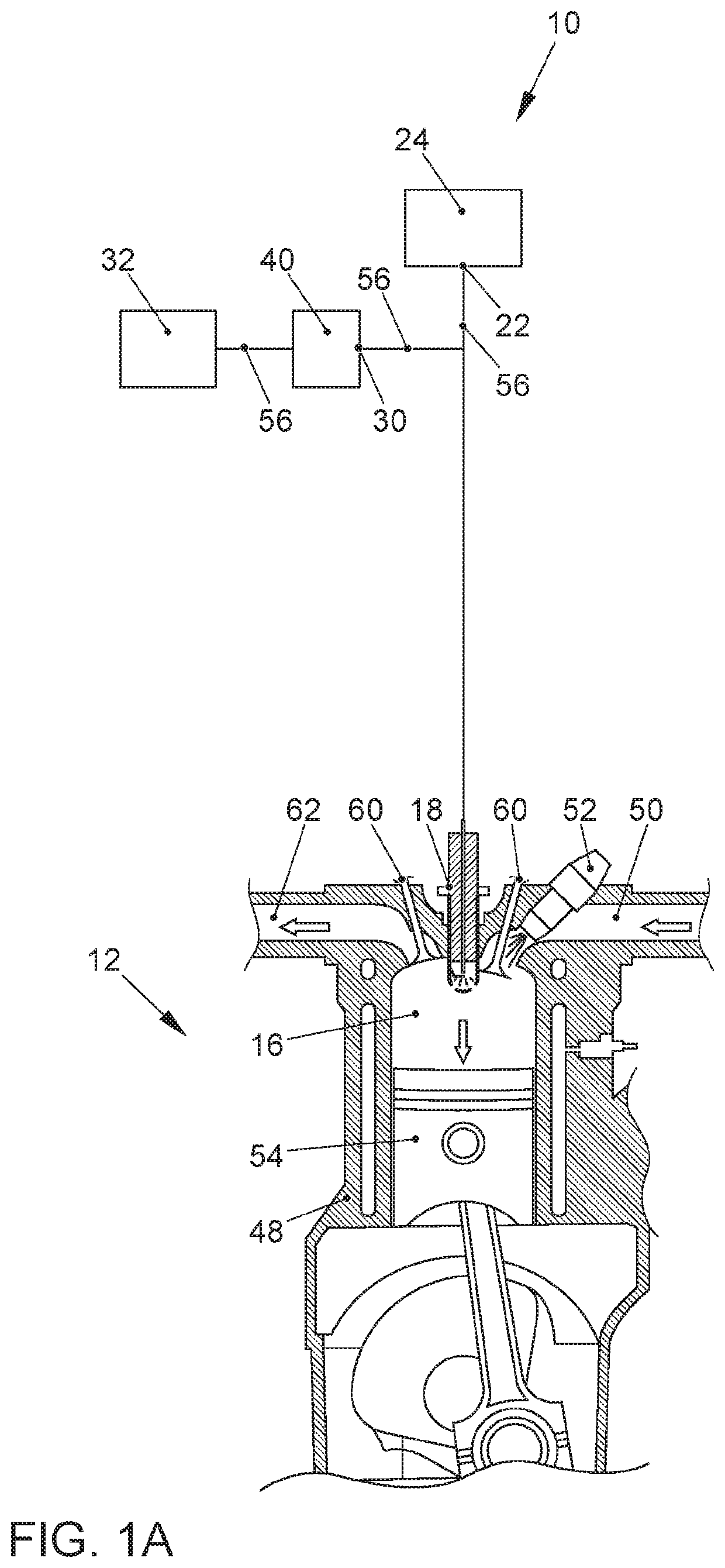
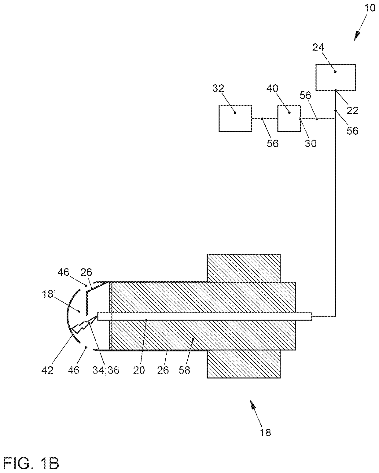
[0059]In an overall view, FIGS. 1A and 1B show a prechamber spark plug 18 of an ignition system 10, which is configured in a combustion chamber 16 of combustion engine 12, and which, besides prechamber spark plug 18, includes as the ignition installation for spark ignition, in particular an ignition coil 24, a high-frequency generator 32 and a power amplifier 40.

[0060]Prechamber spark plug 18 includes a first electrode 20, in particular in the form of a center electrode, and a prechamber 18′ and a second electrode 26 as a ground electrode.

[0061]Spark plug 18, in particular the prechamber spark plug, has at least one opening 46 in a cap 42, so that a prechamber 18′ of prechamber spark plug 18 is disposed between cap 42 and first electrode 20. Via the at least one opening 46, prechamber 18′, which forms a prechamber ignition space, communicates with main combustion chamber 16 (compare FIG. 1A).

[0062]Injector 52 performs the injection of a fuel into main combustion chamber 16 (compare ...

second specific embodiment

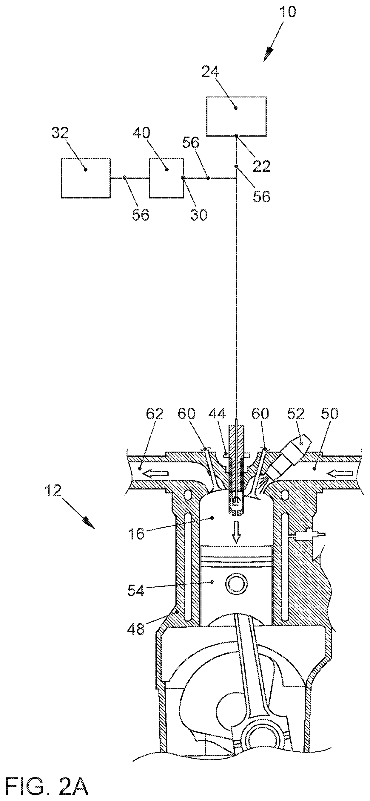
[0072]In an overall view, FIGS. 2A and 2B show a top electrode spark plug 44 of an ignition system 10, which is configured in a combustion chamber 16 of combustion engine 12 and which, analogously to the first specific embodiment, besides top electrode spark plug 44, includes an ignition coil 24, a high-frequency generator 32 and a power amplifier 40 as the ignition installation for spark ignition of top electrode spark plug 44.

[0073]Top electrode spark plug 44 includes a first electrode 20, in particular in the form of a center electrode, and a prechamber 44′ and a second electrode 26 as a ground electrode.

[0074]Top electrode spark plug 44 is equipped with prechamber 44′ having at least one opening 44′-1. Prechamber 44′, which forms a prechamber ignition space, communicates via the least one opening 44′-1 with main combustion chamber 16 (compare FIG. 2A).

[0075]Injector 52 performs the injection of a fuel into main combustion chamber 16 (compare FIG. 1A). In response to the injectio...


PUM


Abstract

An ignition system and a method for a spark-ignition combustion engine having a high-frequency plasma-augmented ignition spark, the spark ignition of the fuel being realized by at least one spark plug associated with a combustion chamber of the combustion engine. The spark plug has a prechamber having at least one opening via which the prechamber communicates with the combustion chamber on the fuel side, so that the ignition spark in the prechamber, into which the high-frequency plasma can be injected, induces the plasma-augmented spark ignition of the fuel in the prechamber.

Description

FIELD OF THE INVENTION[0001]The present invention relates to an ignition method and an ignition system, which is adapted for implementing the ignition method for igniting a fuel-air mixture or a fuel-air-exhaust gas mixture of a combustion engine having externally supplied ignition, in particular a spark-ignition engine.BACKGROUND OF THE INVENTION[0002]A combustion engine is known that has a prechamber configured between the combustion chamber and the intake manifold. The fuel is injected into the prechamber or, in some instances, also directly into the combustion chamber, so that the induced and compressed combustion air is used to prepare a fuel-air mixture. A spark plug, located in the prechamber, is referred to as a prechamber spark plug.[0003]Between the electrode and ground, a high-voltage source, preferably configured as an ignition coil, provides a high-voltage pulse which causes a flashover between the electrode and the grounding contact. The ignition spark leads to an igni...

Claims


Application Information

Patent Timeline
IPC IPC(8): F02P9/00H01T13/40H01T13/50
CPCF02P9/007H01T13/40H01T13/50F02P23/04F02P3/01F02P1/08F02P9/00F02P15/00H01T13/54F02B19/1023F02P23/045F02B19/12
Inventor MICHELS, KARSTENFUCHS, MARTIN
Owner VOLKSWAGEN AG
Learn More