
Innovative solutions for improving laser damage performance of multi-layer dielectric gratings

a dielectric grating and multi-layer technology, applied in the field of multi-layer dielectric coatings, can solve the problems of high efficiency, low laser damage threshold (lidt) of the coating, and the limiting factor of such devices, so as to improve the performance of multi-layer dielectric gratings, improve laser damage threshold, and reduce absorption

Pending Publication Date: 2020-03-26
LAWRENCE LIVERMORE NAT SECURITY LLC
View PDF2 Cites 1 Cited by
  • Summary
  • Abstract
  • Description
  • Claims
  • Application Information

AI Technical Summary

Benefits of technology

This patent text describes an invention that improves the performance of multi-layer dielectric gratings (MDGs) used in laser systems. The invention increases the laser damage threshold, reduces absorption, and increases diffraction efficiency. This allows for significant scaling in output energy and average power for the next generation of ultrafast and spectrally-combined laser systems. The invention also provides new optical thin film designs with significantly improved laser damage thresholds and ultra-low-loss. Multilayer dielectric optical film stacks with improved laser damage thresholds and ultra-low-loss are also provided.

Problems solved by technology

The laser induced damage threshold (LIDT) of the coatings is usually the limiting factor of such devices.
In high-power applications, thin-film dielectric coatings are especially important because they are often the limiting factor driving performance.
The optics used in all these laser systems require low losses, high efficiency, low absorption, precise spectral optical properties and high laser damage thresholds.
Many factors influence laser damage in optics.
One of the most common causes of catastrophic failure is the absorption of energy through gross defect sites on the coating itself.
Thus, surface preparation (including polishing) and coating quality are major factors that limit performance.
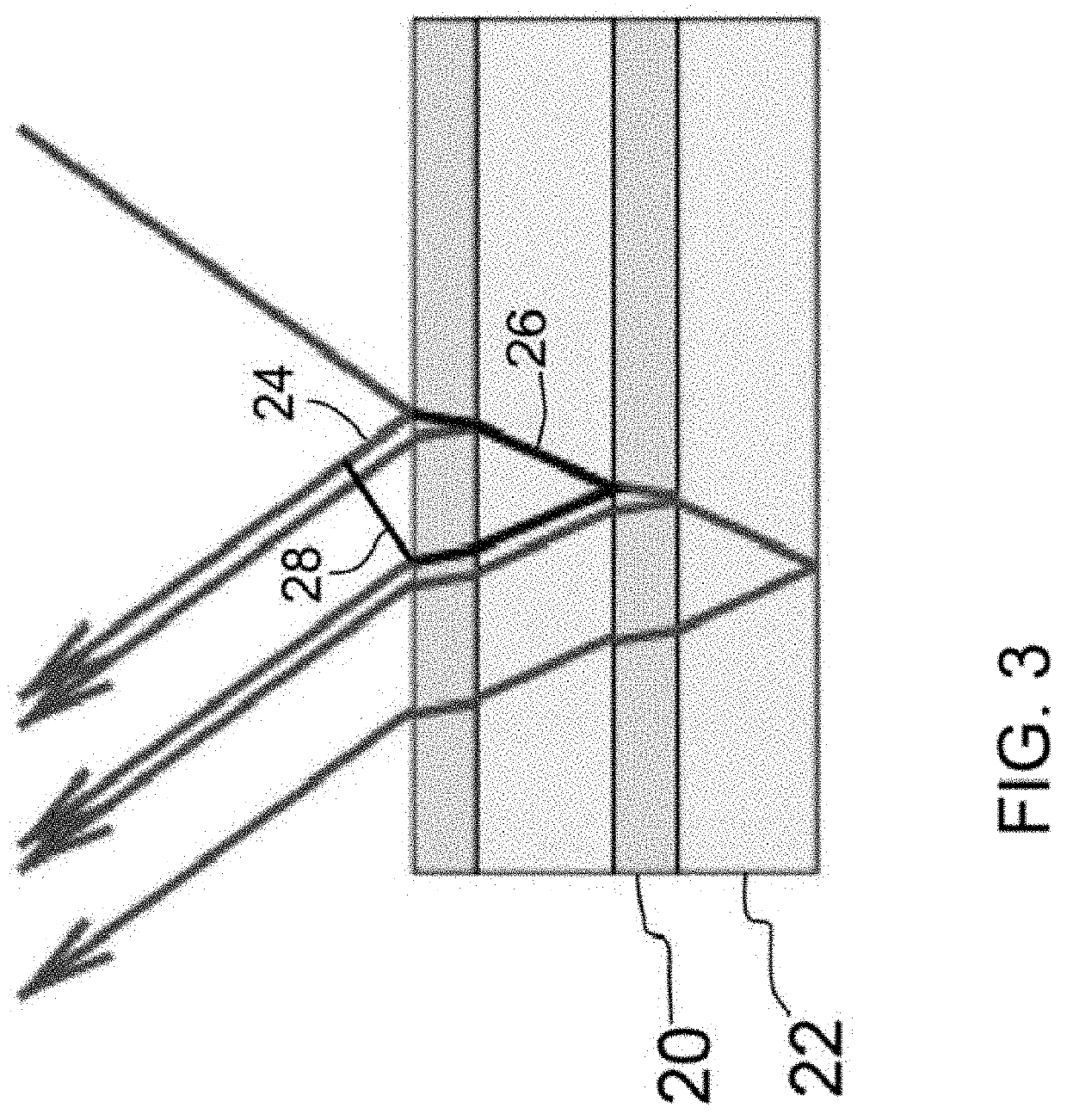
Energy absorption generates heat that causes localized melting, thermal stress fractures, or, if sufficient heat is generated, a small explosion that ablates the coating.
The power densities and thermal loads on this optical element are the limiting factor in power scaling of the technology.
Current grating designs have significant limitations in overall power handling.

Method used


Image

  • Innovative solutions for improving laser damage performance of multi-layer dielectric gratings
  • Innovative solutions for improving laser damage performance of multi-layer dielectric gratings
  • Innovative solutions for improving laser damage performance of multi-layer dielectric gratings

Examples


Embodiment Construction

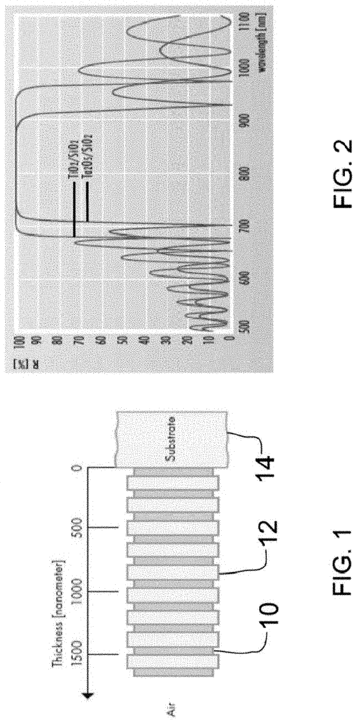
[0016]The Diffractive Optics Group of the National Ignition Facility (NIF) Directorate at Lawrence Livermore National Laboratory (LLNL) is the preeminent supplier of large-aperture, high damage-threshold diffraction gratings and other diffractive optics to laser institutions around the world. Presently, the LLNL group is the only supplier of polarization insensitive Spectral Beam Combining (SBC) gratings. These gratings, designed for polarization independent operation at nominally 1 μm and with a Littrow out-of-plane (conical) mounting, have been shown to have >98% diffraction efficiency over >40 nm bandwidth.

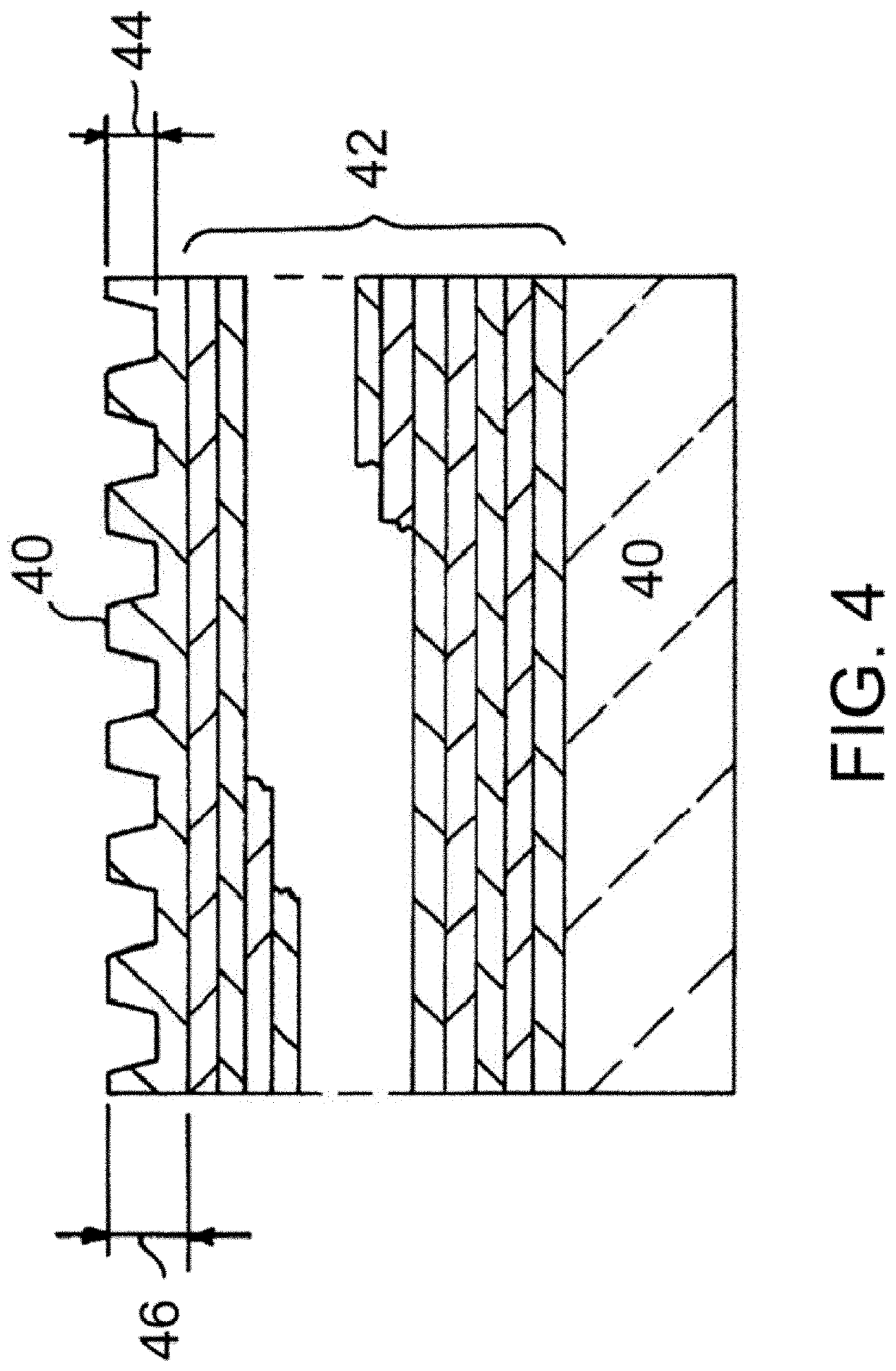
[0017]The current (prior art) grating designs, have significant laser damage threshold limitations and overall power handling limitations due to the high-index, low bandgap, material utilized in the “grating pillars” such as Ta2O5 and HfO2. Laser damage thresholds are highly dependent on the effective bandgap of the dielectric material. The reason for the bandgap dependence app...


PUM

PropertyMeasurementUnit
refractive indexaaaaaaaaaa
band gapaaaaaaaaaa
thicknessaaaaaaaaaa

Abstract

Optical thin film designs are provided that achieve significantly improved laser damage thresholds and ultra-low-loss. These advances may be achieved by utilizing materials with electronic band gaps and refractive indices that are higher than those that are conventionally used.

Description

CROSS-REFERENCE TO RELATED APPLICATIONS[0001]This application is a continuation-in-part of PCT / US2018 / 034497 titled “Innovative Solutions for Improving Laser Damage Performance of Multi-Layer Dielectric Gratings,” filed May 24, 2018, incorporated herein by reference. PCT / US2018 / 034497 claims the benefit of U.S. Provisional Patent Application No. 62 / 514,707 titled “Innovative Solutions for Improving Laser Damage Performance of Multi-Layer Dielectric Gratings,” filed Jun. 2, 2017, incorporated herein by reference.STATEMENT AS TO RIGHTS TO INVENTIONS MADE UNDER FEDERALLY SPONSORED RESEARCH OR DEVELOPMENT[0002]The United States Government has rights in this invention pursuant to Contract No. DE-AC52-07NA27344 between the United States Department of Energy and Lawrence Livermore National Security, LLC, for the operation of Lawrence Livermore National Laboratory.BACKGROUND OF THE INVENTIONField of the Invention[0003]The present invention relates to multi-layer dielectric coatings, and mor...

Claims


Application Information

Patent Timeline
Patent Type & Authority Applications(United States)
IPC IPC(8): G02B5/18G02B1/11
CPCG02B5/1847G02B5/1833G02B1/11G02B5/0833G02B5/18G02B5/285C03C2217/734G02B1/14
Inventor NGUYEN, HOANG T.
Owner LAWRENCE LIVERMORE NAT SECURITY LLC
Learn More