
Hand-depressing vacuum pumping device

a vacuum pumping device and hand-operated technology, applied in the direction of spraying apparatus, liquid spraying apparatus, etc., can solve the problems of troublesome and tedious maintenance service, shutting down further evacuation, troublesome and tedious disassembly process, etc., to save effort and less space , the effect of convenient operation

Inactive Publication Date: 2020-03-26
LIH YANN INDAL
View PDF17 Cites 3 Cited by
  • Summary
  • Abstract
  • Description
  • Claims
  • Application Information

AI Technical Summary

Benefits of technology

The present invention is a hand-depressing vacuum pumping device that comprises a pump unit which is operated through depression or downward pressing. The device has a simple and easy-to-operate design that saves effort, occupies less space, and is easy to remove for service. It includes a liquid container with a guide cover and a pump unit connected to the container through a passage. A one-way piston and a bottom are connected to the guide cover, allowing air to be expelled and air or liquid to flow through the piston. The operation of the device is carried out through depressing, making it easy to use with less effort.

Problems solved by technology

This makes maintenance service trouble and tedious.
Drawing in liquid through vacuum suction to an extent of being almost full would cause the float to move upward and thus shut down further evacuation.
However, most of the components are located inside the machine and disassembling is a trouble and tedious process.
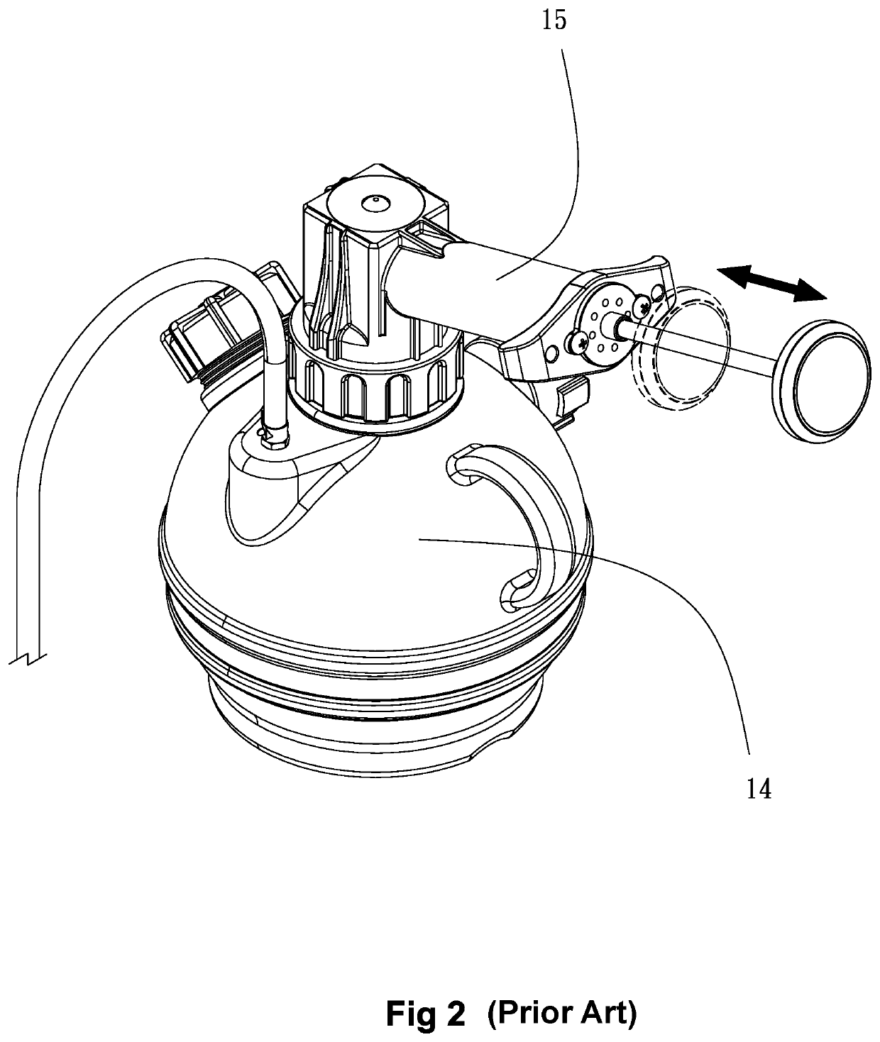
In addition, when the pressure rises to a certain level, the operation of pushing and pulling in the sideway direction would become difficult, and would readily cause tiredness of hands and also problems of immobility.
In consideration of the drawbacks of the prior art discussed above, it is a challenge of those involved in this field to provide a novel structure that helps overcome or alleviates the above problems.

Method used


Image

  • Hand-depressing vacuum pumping device
  • Hand-depressing vacuum pumping device
  • Hand-depressing vacuum pumping device

Examples


Embodiment Construction

[0019]The present invention provides a hand-depressing vacuum pumping device.

[0020]To better expound the purposes, features, and advantages of the present invention, a detailed description will be given below with reference to an embodiment thereof and the drawings.

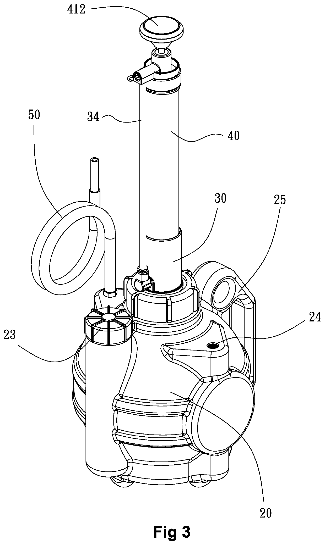
[0021]Referring to FIGS. 4-6, the present invention provides a hand-depressing vacuum pumping device, comprising the following components / parts:

[0022]A liquid container 20 comprises a receiving space 21 formed in an interior thereof

[0023]A guide cover 30 is mounted to a top end of the liquid container 20. The guide cover 30 is formed with a first passage 31 and a second passage 32. The first passage 31 is in communication with the receiving space in the interior of the liquid container 20. The first passage 31 is provided with and coupled to a check valve 33. The first passage 31 is arranged as a by-pass connected to an exposed tube 34.

[0024]A pump cylinder 40 has a top end to which the exposed tube 34 is connected to be ...


PUM


Abstract

A hand-depressing vacuum pumping device includes a liquid container having a top connected to a guide cover, which has a first passage in communication with an interior receiving space of the liquid container, a float-based safety switch, a check valve, and an exposed tube connected to a top of a pump cylinder. The pump cylinder includes a one-way piston arranged therein and the one-way piston is connected to a piston rod and a pressing stem. The pump cylinder has a bottom end connected to a second passage of the guide cover. Depressing the pressing stem downward causes the one-way piston to expel air out and pulling the pressing stem upward causes air to flow from the interior of the liquid container through the one-way piston to the bottom of the pump cylinder so as to evacuate the receiving space of the container to generate vacuum that induces a suction force.

Description

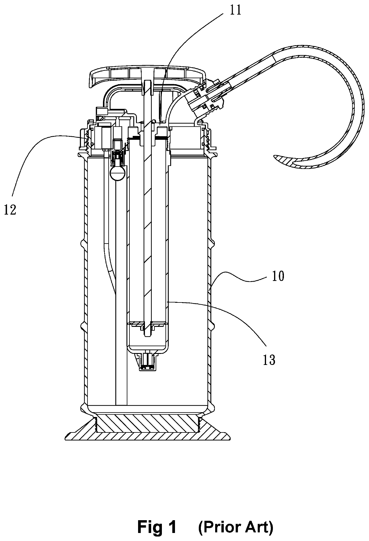
BACKGROUND OF THE INVENTION1. Field of the Invention[0001]The present invention relates to the field of hand-operating pumping devices, and more particularly to a hand-depressing vacuum pumping device, which is easy to operate with less effort and has a pump cylinder that is exposed and detachable and can be readily detached and re-mounted for easy assembly and replacement.2. The Related Arts[0002]FIG. 1 shows a prior art pump proposed in U.S. Pat. No. 9,222,471, owned by the applicant, which discloses a structure of pump including a cap 11 that is fit to an opening of a pump body 10. The pump body 10 has a circumference that is provided with an external thread 23 at a location close to a top thereof to receive a rotatable fixing ring 12 having an internal thread to screw to for fixing so as to secure the cap 11 from the top side and also to rotate about the circumference for threading engagement to fix the cap 11 and the pump body 10 together. The cap 11 is provided with a projecti...

Claims


Application Information

Patent Timeline
Patent Type & Authority Applications(United States)
IPC IPC(8): B05B9/08
CPCB05B9/0816
Inventor LIAO, PO LIN
Owner LIH YANN INDAL
Learn More