
Status signal output

a technology of stat signal and output, which is applied in the field of status, can solve the problems of direct connection of automation devices to at least one control unit or of i/o modules to at least one control unit in the form of parallel wiring, and high cost in design, installation, commissioning and maintenan

Active Publication Date: 2020-03-19
WAGO VERW GMBH
View PDF0 Cites 0 Cited by
  • Summary
  • Abstract
  • Description
  • Claims
  • Application Information

AI Technical Summary

Benefits of technology

[0016]It is therefore an object of the present invention to avoid invalid state messages.
[0021]With the data bus subscriber according to the invention and the conditional change of a status signal value on a status signal line, invalid information about the state is avoided because the status signal value applied to the local bus master is only changed to a value which indicates the communication readiness of the data bus subscribers when all the data bus subscribers are ready to communicate.
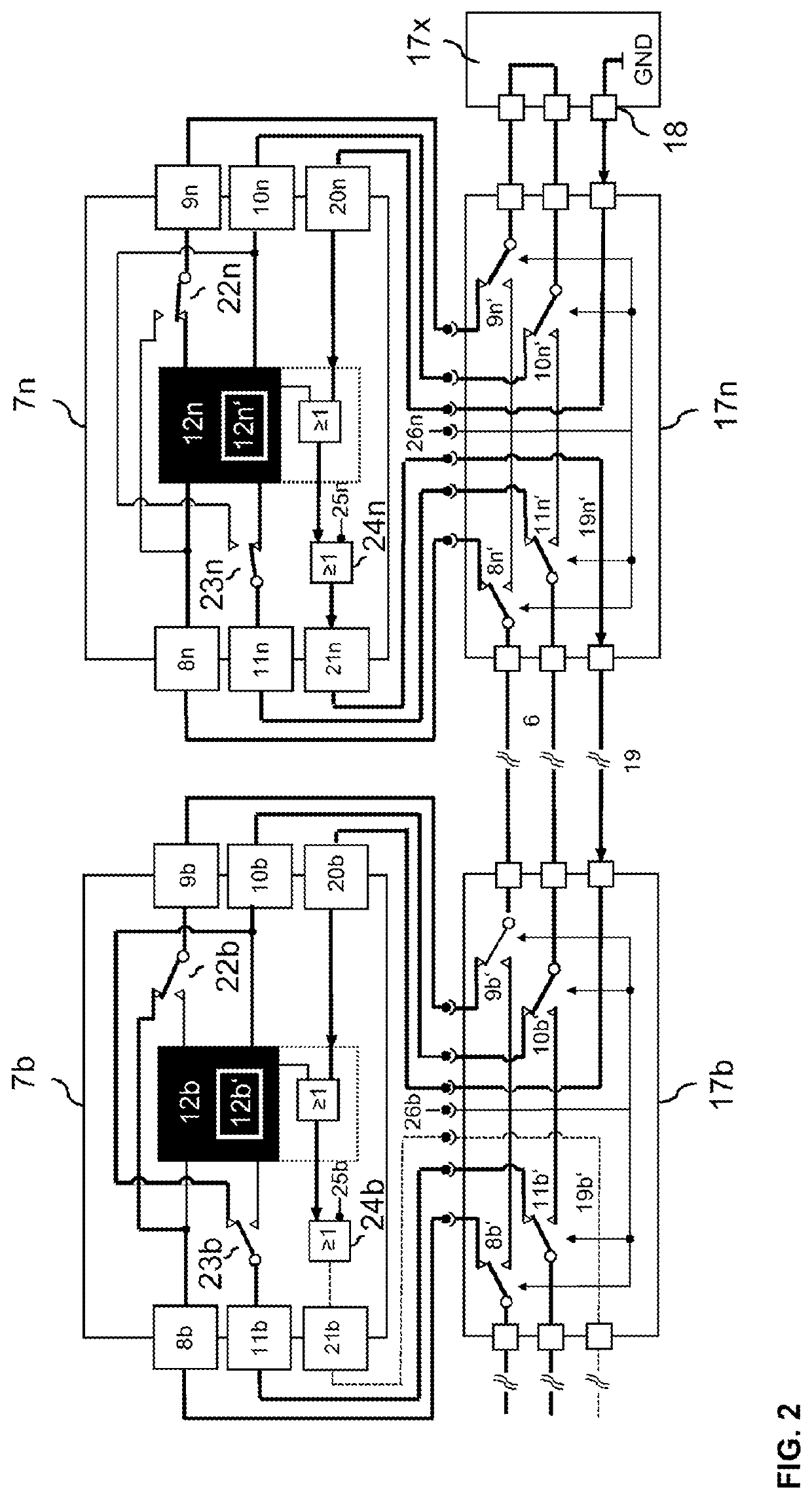
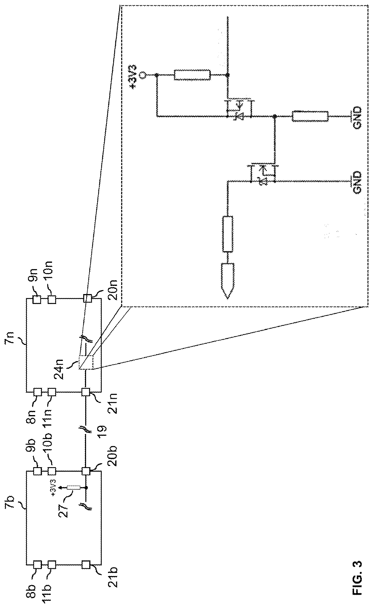
[0026]The data bus subscriber can comprise a controller for changing a resistance value at the status signal output, wherein a change of the resistance value causes a change of the status signal value, or, a transfer of the second status signal value to the upstream data bus subscriber is only possible by the change in the resistance value. The status signal input of a data bus subscriber thereby represents a first resistance value, for example via a pull-up resistor which keeps the status signal input at a certain voltage level. Only when the resistance at the status signal output of the downstream data bus subscriber changes does the status signal input take on the status signal value of the downstream data bus subscriber. As a result, a targeted status signal value transfer is possible without there being any periods in which indeterminate status messages exist because at any given time, a state for the status signal input is defined. Only when all status signal outputs have been changed to corresponding resistance values for forwarding the status signal values does the local bus master receive the status signal and can determine that the local bus is complete and that all data bus subscribers connected to the local bus are ready for communication. This means that only when all data bus subscribers in the local bus have changed their resistance values of the status signal outputs is the status signal present from the last data bus subscriber or the termination unit up to the local bus master. If an error occurs in a data bus subscriber, the status signal is no longer present from the last data bus subscriber or the termination unit to the local bus master. In this case, there is an interruption of the status signal line. Even if the data bus subscribers downstream of the interrupting data bus subscriber pass the status signal or set all their status signal outputs to a predefined status, and the status signal outputs assume resistance values which allow for the status signal to pass through, the status signal is stopped at the interrupting data bus subscriber. Namely, this interrupting data bus subscriber does not set its status signal output to a predetermined state and the status signal output does not assume a specific resistance value, so that the upstream data bus subscriber cannot receive the status signal and therefore does not change its own status signal output. That is, starting from the interrupting data bus subscriber, the status signal outputs are not changed with respect to the provided state and the resistance value. This makes it easy to check whether a local bus is complete and whether the data bus subscribers are all ready to communicate.

Problems solved by technology

However, direct connection of the automation devices to the at least one control unit or of the I / O modules to the at least one control unit in the form of a parallel wiring, i.e., when one line is routed from each automation device or each I / O module to the higher-level control unit, is very expensive.
This is associated with great cost in the design, installation, commissioning and maintenance.
However, the known bus systems and the data bus subscribers connected thereto usually have the disadvantage that the status signal is automatically set to a specific defined state immediately when the data bus subscriber is added.
However, this can lead to invalid states because, for example, the state is already being changed without a corresponding condition having occurred.

Method used


Image

  • Status signal output
  • Status signal output
  • Status signal output

Examples


Embodiment Construction

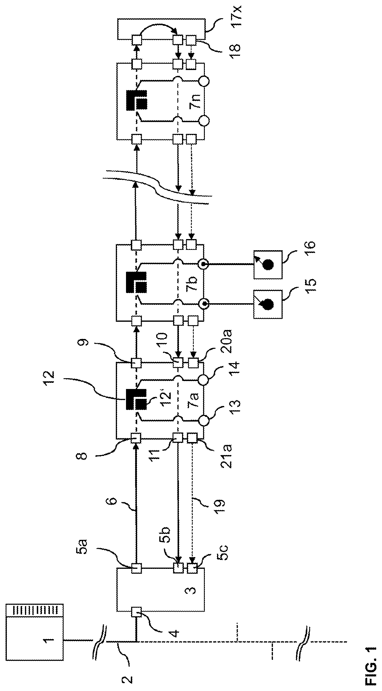
[0041]FIG. 1 shows a schematic block diagram of an automation system. It will be understood by the person skilled in the art that the automation system shown is only an example and all the elements, modules, components, subscribers and units belonging to the automation system can be configured differently but can nevertheless fulfill the basic functions described herein.

[0042]The automation system shown in FIG. 1 has a higher-level control 1, which can be realized for example with a programmable logic control unit, PLC. Such a PLC 1 basically serves to control and regulate the process performed by the automation system. However, PLCs 1 in automation systems today also take on more advanced functions, such as visualization, alerts and recording of all data relating to the process, and as such, the PLC 1 functions as a human-machine interface. There are PLCs 1 with different performance levels, which have different resources (computing capacity, memory capacity, number and type of inp...


PUM


Abstract

A data bus subscriber connected to a local bus, particularly a ring bus. The data bus subscriber has a status signal input for receiving a first status signal value from a downstream data bus subscriber or a terminator, a status signal output for providing a second status signal value to an upstream data bus subscriber or to a local bus master, wherein the data bus subscriber is adapted to provide the second status signal value based on a logical link of a communication readiness of the data bus subscriber and the first status signal value. The invention further relates to a corresponding method and a local bus.

Description

[0001]This nonprovisional application is a continuation of International Application No. PCT / EP2018 / 062962, which was filed on May 17, 2018, and which claims priority to German Patent Application No. 10 2017 208 836.2, which was filed in Germany on May 24, 2017, and which are both herein incorporated by reference.BACKGROUND OF THE INVENTIONField of the Invention[0002]The present invention relates to a data bus subscriber for use on a local bus, in particular a data bus subscriber with a status signal output for checking the completeness and operability of the local bus.Description of the Background Art[0003]Data bus subscribers are mostly used in automation systems.[0004]Automation systems are used in particular for the control of industrial installations, buildings and means of transport. For the control of an automation system, usually several sensors and actuators are necessary. These monitor and control the process performed by the installation. The different sensors and actuato...

Claims


Application Information

Patent Timeline
IPC IPC(8): G06F13/42G06F13/374H04L12/40H04L12/42
CPCH04L12/42H04L12/40019H04L12/40032G06F13/4243G06F13/374H04L12/40006H04L12/40169
Inventor JEROLM, DANIELKIRSTE, HANS-HERBERTSCHADDE, FRANKHUSE, GERALD
Owner WAGO VERW GMBH
Learn More