
Cantilever umbrella

a cantilever and umbrella technology, applied in the field of outdoor umbrellas, can solve the problems of easy bending or breaking of the ribs, difficult to offer a large shaded area by a limited cantilever umbrella, and certainly increases the cost, so as to achieve a new structure, large shading area, and high stability.

Active Publication Date: 2020-02-27
ZHEJIANG DINGSHENG OUTDOOR LIVING PROD CO LTD
View PDF31 Cites 1 Cited by
  • Summary
  • Abstract
  • Description
  • Claims
  • Application Information

AI Technical Summary

Benefits of technology

The present invention provides a cantilever umbrella with a novel structure that has a large shading area and is highly stable. Compared to conventional art, the invention has additional trays that form three canopies, and coordinated rods that allow for folding or unfolding of the canopy fabric. The umbrella is convenient to operate, has a large unfolded area, and can be adjusted to any opening angle. It is also small in volume when folded and highly practical for large outdoor events.

Problems solved by technology

If so, the stress of the canopy fabric borne by the ribs is increased, resulting in instability, easy bending or breakage of the ribs.
In a large applicable place, it is difficult to offer a large shaded area by a limited cantilever umbrella.
If it is to increase the shaded area, multiple umbrellas are needed and this certainly increases the cost.
Additionally, such an umbrella is outdated in style and less novel.

Method used


Image

  • Cantilever umbrella
  • Cantilever umbrella
  • Cantilever umbrella

Examples


Embodiment Construction

[0032]In the following detailed description of the preferred embodiments, reference is made to the accompanying drawings which form a part hereof, and in which are shown by way of illustration specific embodiments in which the invention may be practiced.

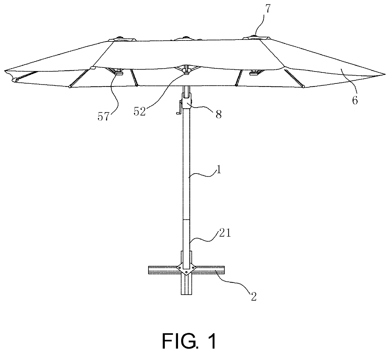
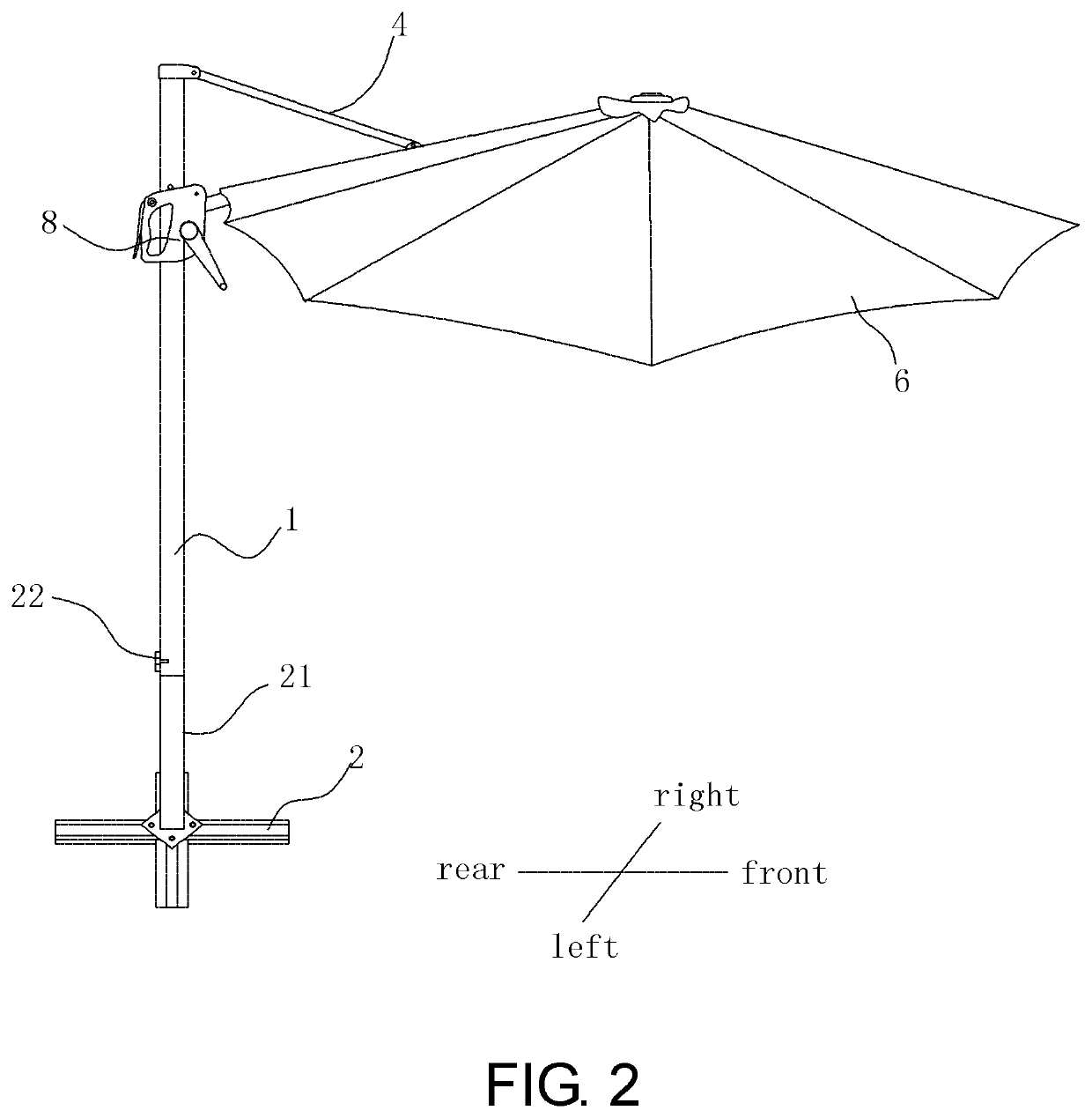
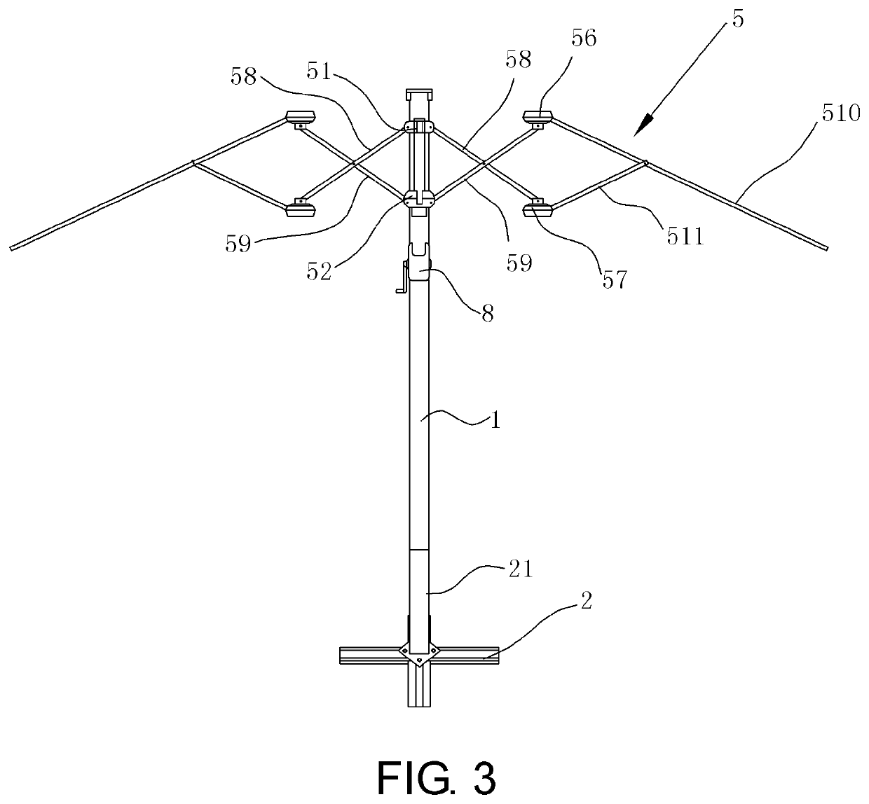
[0033]As shown in FIG. 1 to FIG. 13, a cantilever umbrella including a base 2, a stand 1 disposed on the base 2, a transverse rod 3 with an upper end, a lower end and a middle portion, a drawing rod 4 with a front end and a rear end, a frame 5 having an upper tray 51 and a lower tray 52, which are connected by a hanger rod 53 with a left side, a right side, a front side and a rear side, and a canopy fabric 6 is provided. An upright tube 21 is disposed on the base 2, a screw hole is formed on the upright tube 21 in a radial direction, a corresponding threaded hole is formed at a lower end of the stand 1, and the stand 1 is inserted in the upright tube 2 and fixed by hand-operated screws 22. The lower end of the transverse rod 3 is dis...


PUM


Abstract

A cantilever umbrella including a frame having an upper tray and a lower tray is provided. Two first crossed rods, a transverse rod and a first long rib are articulated to the upper tray. Two second crossed rods and two first short ribs are articulated to the lower tray. One of the two first short ribs is articulated to a middle portion of the transverse rod and the other one is articulated to a middle portion of the first long rib. A middle portion of each second crossed rod is articulated to a middle portion of the first crossed rod on a same side. An end of each first crossed rod is articulated with a short-rib tray which is articulated to a short rib, and an end of each second crossed rod is articulated with a long-rib tray which is articulated to a long rib. The short ribs each has one end articulated to the short-rib tray and another end articulated to a middle portion of one of the long ribs. The upper tray and the two long-rib trays are each disposed with a cap thereon, and a canopy fabric is covered on the long ribs to form three canopies.

Description

CROSS-REFERENCE TO RELATED APPLICATION[0001]This application claims benefit to Chinese Patent Application for a volute for a cantilever umbrella, 201810960961.5, filed on Aug. 22, 2018. The specification of the application is incorporated here by this reference.TECHNICAL FIELD OF THE INVENTION[0002]The present invention relates to the technical field of outdoor umbrellas and in particular to a cantilever umbrella.BACKGROUND OF THE INVENTION[0003]Umbrellas, belonging to leisure items, are mainly used in squares, beaches, parks, gardens or similar places, to shield an individual from sun or rain. Generally, umbrellas include center-support umbrellas and side-support umbrellas. The side support umbrellas include upright-pole cantilever umbrellas which are popular with people due to their convenience in usage, storage and transportation. The demands for such upright-pole cantilever umbrellas are increasing. With the improvement of living standards, cantilever umbrellas with high portabi...

Claims


Application Information

Patent Timeline
IPC IPC(8): E04H15/28E04H15/50A45B23/00
CPCA45B2023/0056A45B23/00E04H15/50A45B2023/0012A45B2023/005E04H15/28A45B25/00A45B25/02A45B25/06A45B25/18A45B2023/0031A45B2023/0093A45B17/00A45B25/14A45B2023/0043A45B2025/146A45B2011/005A45B2023/0037
Inventor KONG, CHENGXI
Owner ZHEJIANG DINGSHENG OUTDOOR LIVING PROD CO LTD
Learn More