Control device, grease cooling method and management device
a technology of control device and management device, which is applied in the direction of programmed control, programmed manipulators, instruments, etc., can solve the problems of increasing cost and enlarging the motor size, and achieve the effect of increasing cos
- Summary
- Abstract
- Description
- Claims
- Application Information
AI Technical Summary
Benefits of technology
Problems solved by technology
Method used
Image
Examples
embodiment
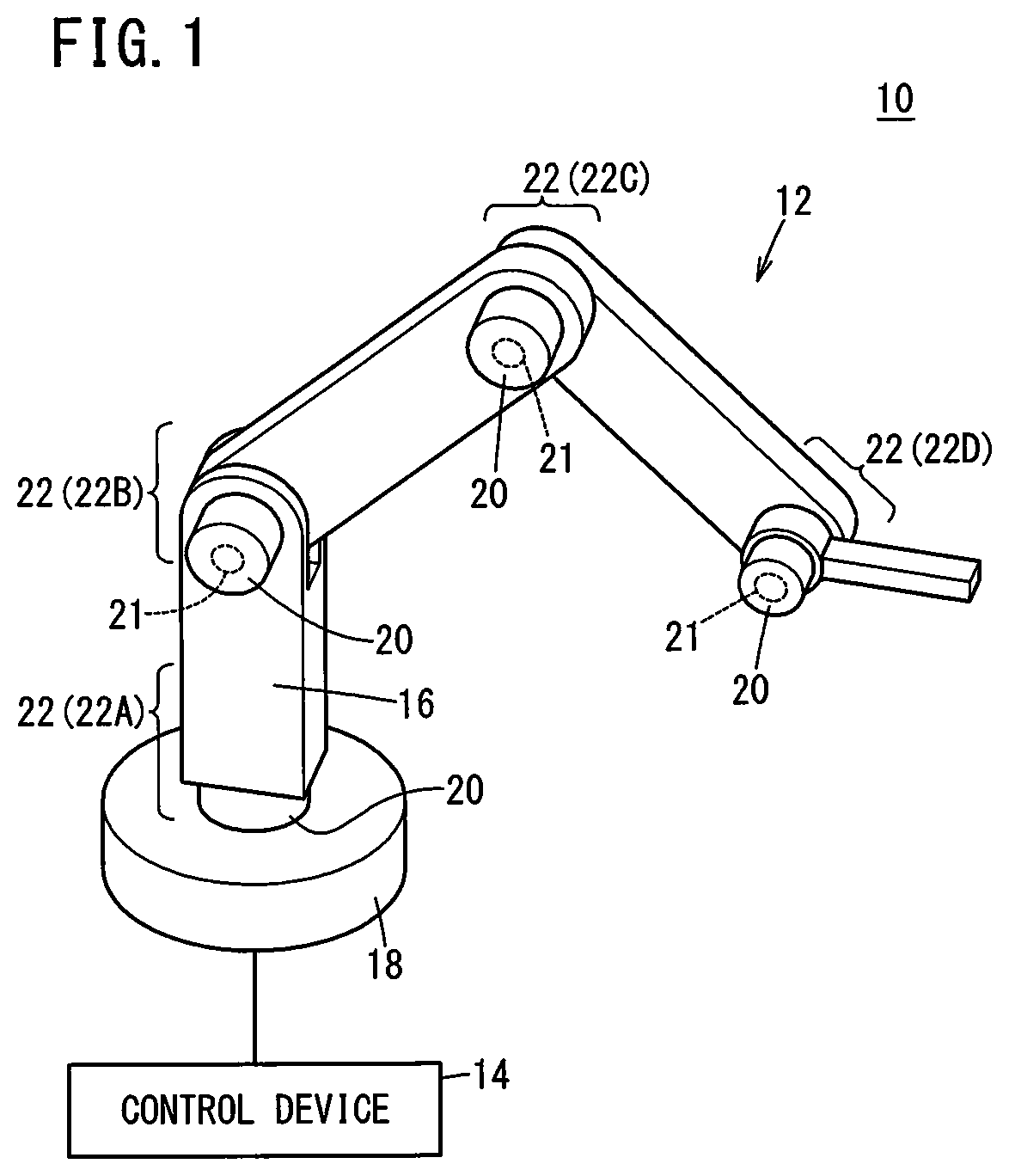
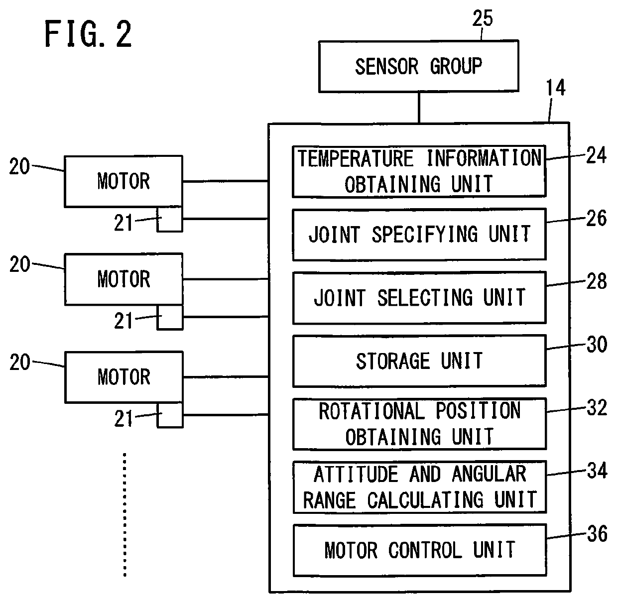
[0018]FIG. 1 is a diagram illustrating the schematic structure of a robot control system 10 according to this embodiment. The robot control system 10 includes a robot 12, a control device 14 for controlling the robot 12, and so on.
[0019]The robot 12 includes an articulated arm 16, a base 18 for supporting the articulated arm 16, and so on. The articulated arm 16 includes a plurality of joints 22 that are turned by driving of motors 20. The control device 14 drives the motors 20 as needed to turn the joints 22.
[0020]Each joint 22 includes the motor 20, a reducer (not shown), a bearing (not shown), grease (a lubricant: not shown) for lubricating operation of the bearing, and so on. The motors 20 are capable of forward rotation and reverse rotation, and they transfer power to the reducers to turn the joints 22. Each motor 20 includes an encoder 21 for measuring a rotational position, and so on. The joints 22 of the articulated arm 16 are denoted as joint 22A, joint 22B, joint 22C, and ...
first modification
[First Modification]
[0048]In the embodiment above, the information indicating the operation permitted area is predetermined. However, if a new interfering object, which was not there before, is placed around the robot 12, for example, the operation permitted area changes and interference may occur between the articulated arm 16 and the interfering object. In order to prevent such interference, as shown in FIG. 4, a control device 14 of this modification further includes an interfering object information obtaining unit 38, an area calculating unit 40, etc. The same constituent elements as those of the control device 14 of the embodiment above are labeled using the same reference numerals and different constituent elements will be described below.
[0049]The interfering object information obtaining unit 38 is configured to obtain interfering object information indicating the size, position, shape, etc. of an interfering object present around the robot 12, from cameras etc. (not shown) p...
second modification
(Second Modification)
[0052]The control device 14 of the first modification above includes the one area calculating unit 40 and it calculates information indicating an operation permitted area. However, if the single area calculating unit 40 calculates wrong information about the operation permitted area, then interference may occur between the articulated arm 16 and the interfering object. A control device 14 of this modification prevents interference between the articulated arm 16 and interfering object if a problem occurs in the calculation of information indicating the operation permitted area.
[0053]The control device 14 of this modification includes a plurality of the area calculating units 40. When the pieces of information indicating the operation permitted area calculated respectively by the plurality of area calculating units 40 are equal, then the attitude and angular range calculating unit 34 calculates the range of rotational angle of the motor 20 of the selected joint 22...
PUM
 Abstract
Description
Claims
Application Information
 - R&D
- Intellectual Property
- Life Sciences
- Materials
- Tech Scout
- Unparalleled Data Quality
- Higher Quality Content
- 60% Fewer Hallucinations
Browse by: Latest US Patents, China's latest patents, Technical Efficacy Thesaurus, Application Domain, Technology Topic, Popular Technical Reports.
© 2025 PatSnap. All rights reserved.Legal|Privacy policy|Modern Slavery Act Transparency Statement|Sitemap|About US| Contact US: help@patsnap.com


