
RFID or Biometric Locking Mechanism Fitted on a Concealed Pocket of a Container Operated via a Mobile Application or Through an RFID Article or Other Biometric Technologies

a biometric and container technology, applied in the field of concealed container and accessing locking mechanisms, to achieve the effect of quick and automatic unlocking, faster drawing of an article, and efficient and effective work

Inactive Publication Date: 2020-01-30
ARNOLD DELBERT CLEVELAND
View PDF2 Cites 9 Cited by
  • Summary
  • Abstract
  • Description
  • Claims
  • Application Information

AI Technical Summary

Benefits of technology

The present invention is a fail-secure locking mechanism for a concealed carry weapon (CCW) container that allows users to securely lock the container and access its contents using biometric technology or RFID tags. The container features a panic switch, ballistic armor plate, and a locking mechanism to ensure that the container remains locked even in the absence of power. The container is well lit up to allow for easy identification in dark environments or in emergency situations. The method and system also allow users to manage the locking mechanism using a mobile app or RFID tag, and detect unauthorized access or tampering with the container. The fail-secure lock apparatus provides an accountable and mobile security storage solution for users who need quick access to the container in emergency situations.

Problems solved by technology

Presently, gun safes and similar reinforced storages are generally stationary or elsewise require a dedicated key that can be misplaced or difficult to handle in certain situations.

Method used


Image

  • RFID or Biometric Locking Mechanism Fitted on a Concealed Pocket of a Container Operated via a Mobile Application or Through an RFID Article or Other Biometric Technologies
  • RFID or Biometric Locking Mechanism Fitted on a Concealed Pocket of a Container Operated via a Mobile Application or Through an RFID Article or Other Biometric Technologies
  • RFID or Biometric Locking Mechanism Fitted on a Concealed Pocket of a Container Operated via a Mobile Application or Through an RFID Article or Other Biometric Technologies

Examples


Embodiment Construction

[0029]All illustrations of the drawings are for the purpose of describing selected versions of the present invention and are not intended to limit the scope of the present invention.

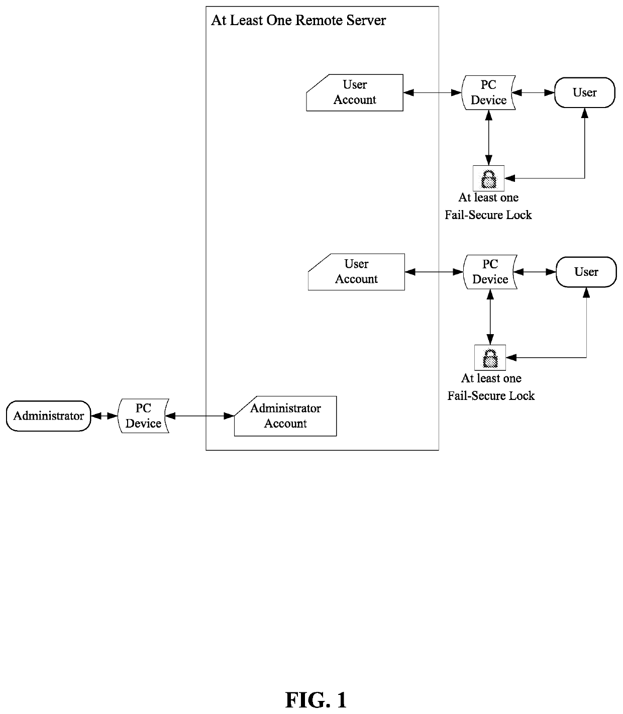
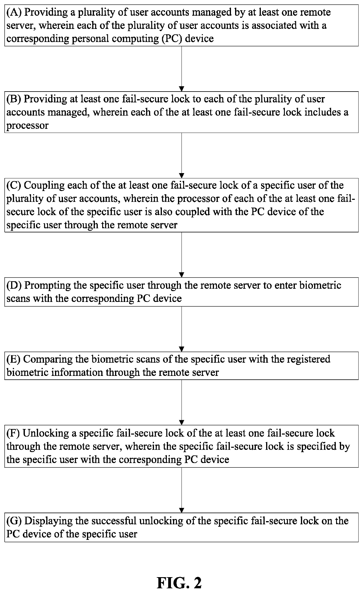
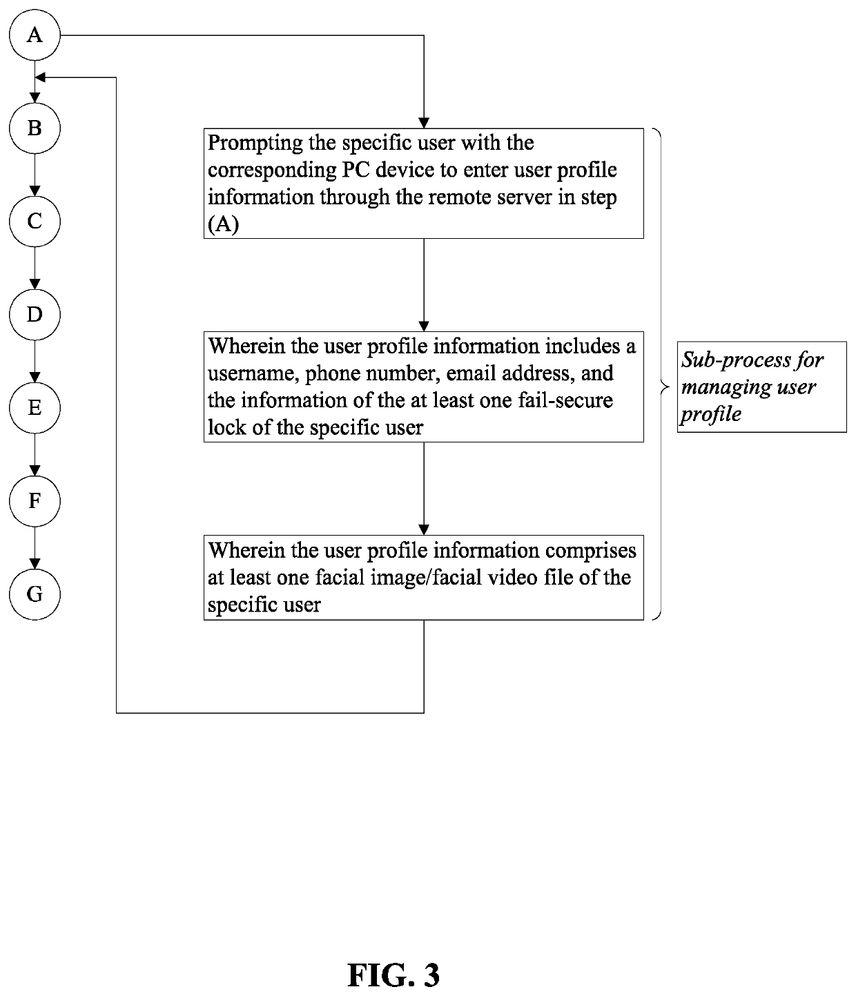
[0030]As can be seen in FIG. 1 to FIG. 14, the present invention provides a method and system to a user to manage a fail-secure locking mechanism using a mobile app on a personal computing (PC) device, or at least one RFID tag, or any other biometric technology. The fail-secure locking mechanism may be fitted on a concealed pocket of a container, which may include, but is not limited to, a bag, a concealed carry weapon (CCW) bag, a handbag, a backpack, a sling bag, a laptop bag, a bank bag, a messenger bag, a jewelry bag, a suitcase, a box, a security box, a locker, a safe, a door, etc. The container and PC device possess visual acquisition means to authenticate the user in lieu of or alongside at least one RFID tag. Additionally, the method and system of the present invention can determine if the specif...


PUM


Abstract

A concealed carry weapon (CCW) container offers a user a fail-secure locking mechanism to ensure that the CCW stays locked at all times even when there is no power. The CCW container enables the user to quickly and automatically unlock when the user utilizes the biometric recognition system, a pass code, or an RFID (Radio Frequency Identification) tag. The CCW container employs interior and exterior lighting, quick access magnetic closure with or without a locking mechanism attached, and a ballistic armor plate to protect the user's vital body parts using the ballistic armor plat as a shield. Further, a method for managing the fail-secure locking mechanism allows the user to efficiently access the CCW content using a mobile app, the RFID tag, or any other biometric technology. Additionally, the method provides a panic switch that alerts security authorities of an incident and forwarding any salient video or sound thereto.

Description

[0001]The current application claims a priority to the U.S. Provisional Patent application Ser. No. 62 / 703,142 filed on Jul. 25, 2018.FIELD OF THE INVENTION[0002]The present invention relates generally to containers and methods for accessing locking mechanisms. More particularly, the present invention relates to a concealed carry weapon container with a secure closure, a panic switch, a ballistic armor plate and a locking mechanism that is particularly centered around biometrics and RFID (Radio Frequency Identification) authentication. Further, the present invention includes a system and method for managing the locking mechanism thereof.BACKGROUND OF THE INVENTION[0003]Presently, gun safes and similar reinforced storages are generally stationary or elsewise require a dedicated key that can be misplaced or difficult to handle in certain situations. It is therefore the objective of the present invention to provide a protocol and container in connection and synced with a computing devi...

Claims


Application Information

Patent Timeline
IPC IPC(8): G07C9/00G06K7/10
CPCG06K7/10366G07C9/33G07C9/37G07C9/00912G07C9/00563G07C9/00571G07C2009/0092
Inventor ARNOLD, DELBERT CLEVELAND
Owner ARNOLD DELBERT CLEVELAND
Learn More