Bush

a technology for bushes and bushes, applied in the field of bushes, can solve problems such as the possibility of entanglement between bushes and soundproof bushes, and achieve the effect of allowing elastic deformation of the diameter of the bushes main body

Active Publication Date: 2020-01-23
KK TOKAI RIKA DENKI SEISAKUSHO
View PDF0 Cites 0 Cited by
  • Summary
  • Abstract
  • Description
  • Claims
  • Application Information

AI Technical Summary

Benefits of technology

The present invention relates to a bush for a seatbelt device, which has a main body that extends in a circumferential direction of a mounting hole of a supporting part of the seatbelt device, and is supported at the part of the vehicle body. A connection portion connects both circumferential direction sides of the bush main body, allowing elastic deformation of the diameter of the bush main body, and making passage of flange portions through the mounting hole possible. The connection portion can appropriately allow elastic deformation of the diameter of the bush main body, suppressing another bush main body passing-through between the both circumferential direction sides of the bush main body and entangling of bush main bodies. The connection portion can be broken, elastically deformed, or elastically deformed or connect the axial direction intermediate portions of the both circumferential direction sides of the shaft portion. The technical effect of the present invention is to improve the stability and reliability of the seatbelt device.

Problems solved by technology

Here, in this soundproof supporting device, there is the possibility that soundproof bushes will become entangled with one another due a soundproof bush passing-through the cut-out of another soundproof bush.

Method used


Image

  • Bush
  • Bush
  • Bush

Examples


first embodiment

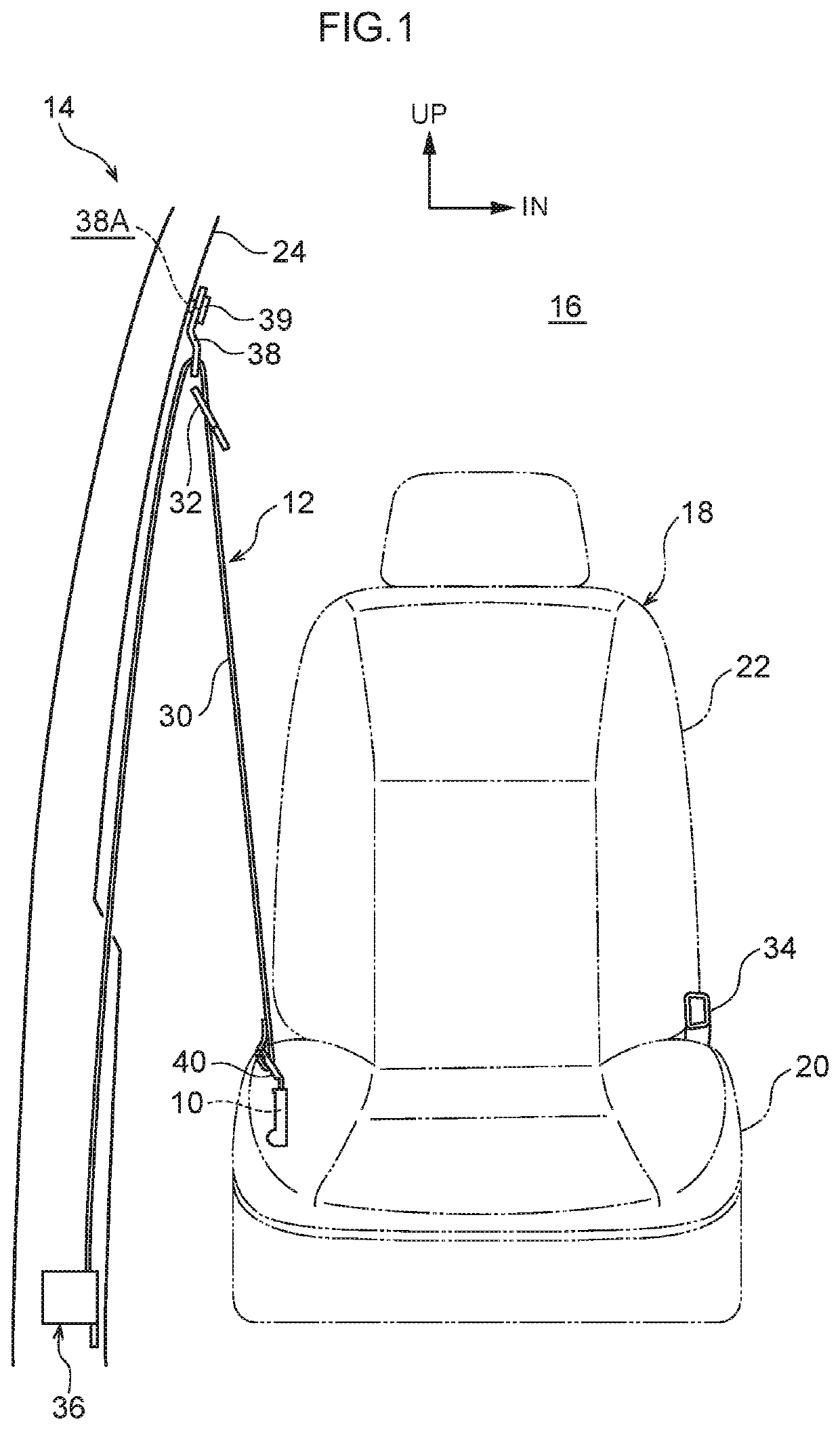
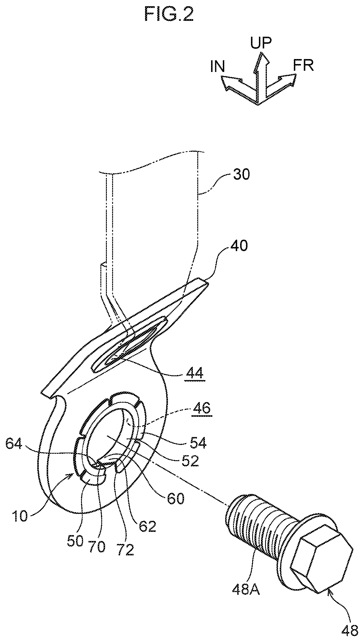
[0021]A bush 10 relating to a first embodiment of the present invention is described hereinafter by using FIG. 1 through FIG. 5.

[0022]A seatbelt device 12, to which the bush 10 relating to the first embodiment of the present invention is applied, is shown in FIG. 1. Note that, in the drawings, the vehicle front side is denoted by arrow FR, the vehicle transverse direction inner side is denoted by arrow IN, and the vehicle upper side is denoted by arrow UP.

[0023]The seatbelt device 12 is provided at a vehicle seat 18 (e.g., the driver's seat or the front passenger's seat). The vehicle seat 18 is disposed within a vehicle cabin 16 of a vehicle 14, and a vehicle occupant can sit in the vehicle seat 18. The vehicle seat 18 is structured to include a seat cushion 20 that is at the vehicle lower side. The seat cushion 20 supports the buttocks and the thighs of the vehicle occupant (not shown). Further, the vehicle seat 18 is structured to include a seatback 22 that is at the vehicle rear ...

second embodiment

[0041]A bush 90 relating to a second embodiment of the present invention is described hereinafter by using FIG. 6. Note that structural portions that are the same as those of the above-described first embodiment are denoted by the same numbers, and description thereof is omitted.

[0042]As shown in FIG. 6, a connection portion 92 of the bush 90 relating to the present embodiment connects, along the circumferential direction, the circumferential direction both ends of the shaft portion 52. Further, the connection portion 92 is formed to be thinner and to have lower rigidity than the shaft portion 52.

[0043]Moreover, in accordance with the bush 90 relating to the present embodiment, due to the connection portion 92 being bendingly deformed and elastically deformed and being moved toward the inner circumferential side of the shaft portion 52, the diameter of the bush main body 50 can be elastically contracted, and the second flange portion 56 (or the first flange portion 54) can pass-thro...


PUM


Abstract

Entanglement of bush main bodies is suppressed. At a bush, a shaft portion of a bush main body, which extends in a circumferential direction of a mounting hole of an outer anchor, covers a peripheral surface of the mounting hole. A first flange portion and a second flange portion of the bush main body are placed on an front and back sides of the outer anchor, respectively. Moreover, a connection portion connects both circumferential direction sides of the bush main body. The connection portion allows elastic deformation of a diameter of the bush main body, and the second flange portion can pass-through the mounting hole.

Description

CROSS-REFERENCE TO RELATED APPLICATION[0001]This application is based on and claims priority under 35 USC 119 from Japanese Patent Application No. 2018-136534 filed on Jul. 20, 2018, the disclosure of which is incorporated by reference herein.BACKGROUNDTechnical Field[0002]The present invention relates to a bush at which a shaft portion and a pair of flange portions are provided.Related Art[0003]In the soundproof supporting device of following Japanese Utility Model Application Laid-Open (JP-U) No. S61-14153, a shaft portion of a soundproof bush covers the peripheral surface of a mounting bolt hole of an anchor hardware, and a pair of flange portions of the soundproof bush cover the front and back sides of the anchor hardware respectively. Further, a cut-out is formed in a circumferential direction portion of the soundproof bush. Due to the cut-out permitting elastic deformation of the diameter of the soundproof bush, the flange portions of the soundproof bush are passed-through the...

Claims


Application Information

Patent Timeline
Patent Type & Authority Applications(United States)
IPC IPC(8): F16C33/08F16C17/02
CPCF16C33/08F16C17/02F16C2326/08B60R22/26B60R2022/263B60R22/023F16C43/02F16C27/02B60R22/18
Inventor YUASA, KAORUMAKINO, GIKO
Owner KK TOKAI RIKA DENKI SEISAKUSHO
Why Eureka
Try Eureka