Chuck Device and Hoop Winding Device

a technology of chuck and hoop, which is applied in the direction of transportation and packaging, thin material processing, filament handling, etc., can solve the problems of high tension applied to the fiber bundles that are held, fiber bundles may fall out, and fluid pressure that can be supplied has a limi

Active Publication Date: 2014-08-14
MURATA MASCH LTD
View PDF17 Cites 3 Cited by
  • Summary
  • Abstract
  • Description
  • Claims
  • Application Information

AI Technical Summary

Benefits of technology

The present invention relates to a chuck device and a hoop winding device for handling fiber bundles. The chuck device includes a pair of hands that can hold the fiber bundle tightly with tension applied, while the hoop winding device includes the chuck device and a resting liner or bobbin around which the fiber bundle is wound. The technical effects of this invention include secure holding of the fiber bundle, easy adjustment of tension, reduced damage to the fiber bundles during handling, and facilitation of winding process.

Problems solved by technology

However, high tension is applied on the fiber bundles that are held by the chuck device.
Furthermore, in a case where the chuck device holds the plurality of fiber bundles, some of the fiber bundles may fall out since holding force is not transmitted thereto.
However, the fluid pressure that can be supplied has a limit, and even if the force for sandwiching the fiber bundles was increased, the fiber bundles fell out of the chuck device in some cases when the tension of the fiber bundles was high.
Furthermore, even when a member by which friction to the fiber bundles is increased was mounted to the hands, the fiber bundles fell out of the chuck device in some cases.

Method used


Image

  • Chuck Device and Hoop Winding Device
  • Chuck Device and Hoop Winding Device
  • Chuck Device and Hoop Winding Device

Examples


Embodiment Construction

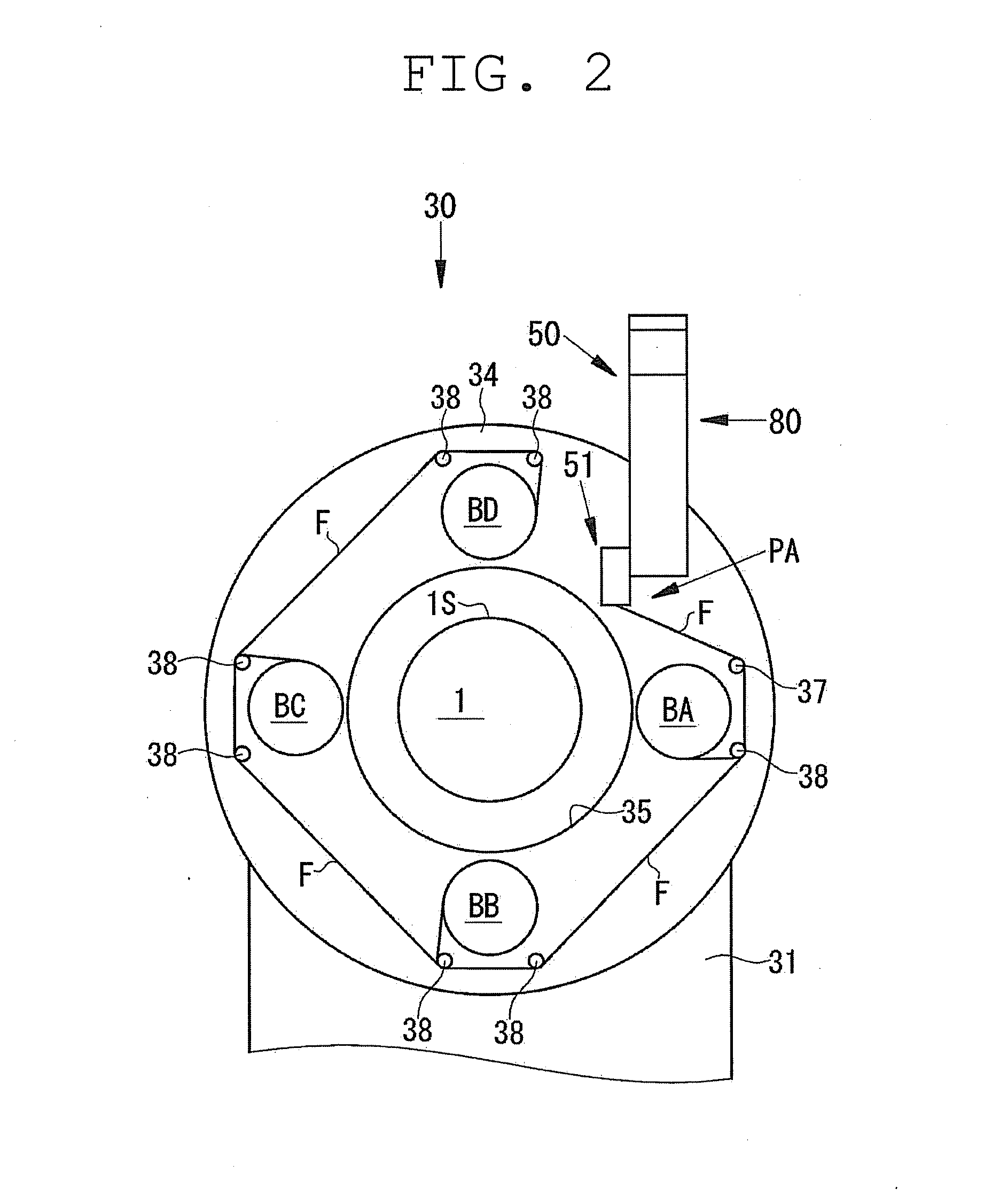
[0036]A chuck device 51 and a hoop winding device 30 according to an embodiment of the present invention will be described with reference to the following drawings. First, an overall configuration of a filament winding apparatus (FW apparatus) 100 will be described with reference to FIG. 1. The FW apparatus 100 is adapted to wind a fiber bundle F impregnated with resin around a liner 1 by repeatedly carrying out hoop winding by the hoop winding device 30 and helical winding by the helical winding device 40 alternately with respect to the liner 1.

[0037]Arrows A, B illustrated in FIG. 1 indicate a front-back direction of the FW apparatus 100 and a transfer direction of the liner 1 in the helical winding. In the helical winding, the liner 1 reciprocates in the front-back direction of the FW apparatus 100, and hence the liner 1 may be transferred in the direction of the arrow A or may be transferred in the direction of the arrow B. In the following description, a leading-end side of the...


PUM

PropertyMeasurementUnit
winding angleaaaaaaaaaa
tensionaaaaaaaaaa
frictionaaaaaaaaaa

Abstract

A chuck device of a fiber bundle includes a pair of hands adapted to be opened / closed. The pair of hands includes a plurality of guides adapted to regulate and bend the fiber bundle under a closing state, and to release the fiber bundle under an opening state. Under the closing state, the plurality of guides holds the fiber bundle by being close to each other with tension applied on the fiber bundle.

Description

CROSS-REFERENCE TO RELATED APPLICATIONS[0001]This application claims priority under 35 U.S.C. 119 to Japanese Patent Application No. 2013-23768, filed on Feb. 8, 2013, which application is hereby incorporated by reference in its entirety.BACKGROUND OF THE INVENTION[0002]1. Field of the Invention[0003]The present invention relates to an art of a chuck device adapted to hold fiber bundles and a hoop winding device including the same.[0004]2. Description of Related Art[0005]There is publicly known a filament winding apparatus (hereinafter appropriately referred to as a “FW apparatus”) adapted to form a reinforcement layer by winding the fiber bundles around the liner (see U.S. Pat. No. 8,403,251, for example). The FW apparatus repeatedly performs a hoop winding by a hoop winding device and a helical winding by a helical winding device alternately with respect to a liner.[0006]The hoop winding device and the helical winding device wind the fiber bundles around the liner while applying a...

Claims


Application Information

Patent Timeline
Patent Type & Authority Applications(United States)
IPC IPC(8): B29C53/80
CPCB29C53/8016B65H59/28B29C2053/8025B65H49/18
Inventor TANIGAWA, MOTOHIROUOZUMI, TADASHINAKAMURA, DAIGOROHATTA, KEN
Owner MURATA MASCH LTD
Why Eureka
Try Eureka