
A fluid trap for a respiratory therapy system

a technology of respiratory therapy and fluid trap, which is applied in the field of fluid trap, can solve the problems of affecting the performance of the breathing circuit, affecting the treatment effect,

Active Publication Date: 2020-01-23
FISHER & PAYKEL HEALTHCARE LTD
View PDF4 Cites 3 Cited by
  • Summary
  • Abstract
  • Description
  • Claims
  • Application Information

AI Technical Summary

Benefits of technology

The present invention provides a fluid trap for a respiratory therapy system that can be reusable or disposable. The fluid trap includes a valve that can be mounted on the container or closure and is in a closed condition to prevent fluid from flowing through the inlet when the closure is not mounted on the container. The valve can be opened to allow fluid to flow into the container when the closure is mounted on the container. The valve has cut-outs or recesses to reduce its weight and flexibility, and a sealing formation that helps engage the closure and container, or the valve and container, in a secure manner. The technical effects of this invention include improving the efficiency and flexibility of the respiratory therapy system.

Problems solved by technology

By way of example, if the reusable fluid trap was to be reassembled incorrectly the breathing circuit may leak, causing a possible drop in treatment pressure or an infection risk.
Additionally, it can be desirable for the fluid trap to have a small compressible volume, as the increase in the compressible volume provided by the fluid trap may result in delay of the pressure waveform reaching the ventilator, throwing off breathing circuit performance.

Method used


Image

  • A fluid trap for a respiratory therapy system
  • A fluid trap for a respiratory therapy system
  • A fluid trap for a respiratory therapy system

Examples


Embodiment Construction

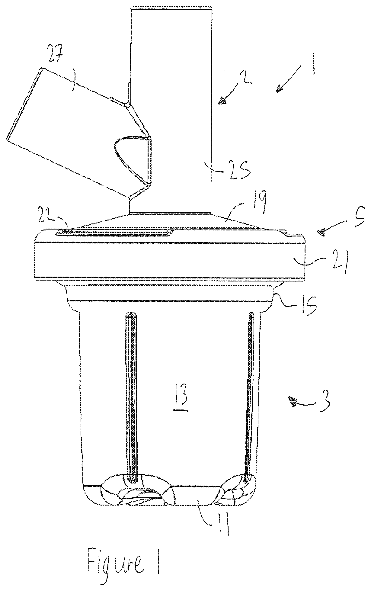
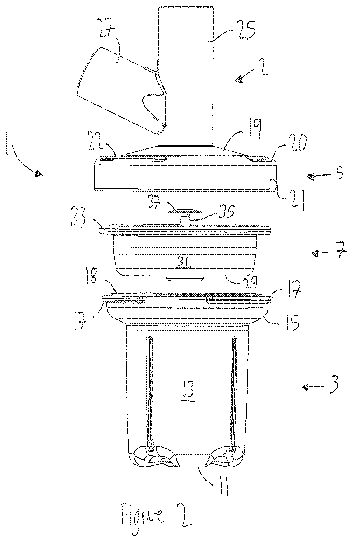
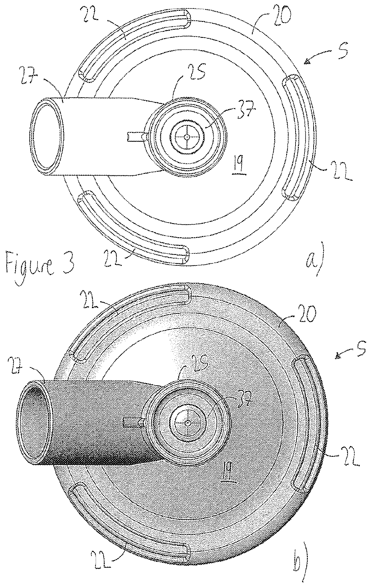
[0097]With reference to the Figures a fluid trap 1 for a breathing limb, such as an expiratory limb, of a respiratory therapy system (not shown) comprises:[0098]at least one inlet 2 configured to be connected to the breathing limb to receive fluid from the breathing limb;[0099]a container 3 configured to contain fluid received from the inlet 2;[0100]a closure 5, the closure 5 and container 3 being configured to be removeably mounted together to close the container 3; and[0101]a valve 7 configured to be removeably mounted on at least one of the container 3 and the closure 5, and configured to be in a closed condition which prevents fluid from being received in the container 3 from the inlet 2 when the closure 5 is not mounted on the container 3, the valve 7 being further configured to be in an open position which allows fluid from the inlet 2 into the container 3 when the closure 5 is mounted on the container 3.

[0102]The container 3 in this example is substantially cylindrical and co...


PUM


Abstract

Disclosed is a fluid trap for use with, or comprising part of, a respiratory therapy system, d particular comprising part of, or configured to be connected to, a breathing limb, such as an expiratory limb, of a respiratory therapy system. The fluid trap comprises a container configured to contain fluid received from an inlet; a closure, the closure and container being configured to be removeably mounted together to close the container; and a valve configured to be removeably mounted on at least one of the container and the closure, and configured to be in a closed condition which prevents fluid from flowing through the inlet when the closure is not mounted on the container, the valve being further configured to be in an open position which allows fluid from the inlet into the container when the closure is mounted on the container.

Description

BACKGROUNDField of the Disclosure[0001]The present disclosure generally relates to a fluid trap for use with, or comprising part of, a respiratory therapy system, and in particular comprising pail of, or configured to be connected to, a breathing limb, such as an expiratory limb, of a respiratory therapy system. This application claims priority from US provisional applications 62 / 461708 filed Feb. 21, 2017 and U.S. 62 / 507065 filed May 16, 2017, the entire contents of both of which are hereby incorporated by reference.Description of the Related Art[0002]A respiratory therapy system typically delivers heated and humidified gases for various medical procedures, including respiratory treatment, laparoscopy and the like. Such a system can be configured to control temperature, humidity and flow rates. Respiratory humidification can also be used in respiratory therapy systems.[0003]A respiratory therapy system is typically used for the treatment of respiratory conditions such as, for examp...

Claims


Application Information

Patent Timeline
Patent Type & Authority Applications(United States)
IPC IPC(8): A61M16/08A61M16/20
CPCA61M16/206A61M16/0808A61M16/0816A61M16/1075A61M16/16A61M16/201A61M16/20A61M39/26A61M2205/0216A61M16/0883A61M2205/581A61M2205/582A61M16/1095A61M2039/246
Inventor GRAY, NATHAN LEEPEIRIS, TELGE NISHAN CHATURANGAMOODY, PAUL JOSEPH
Owner FISHER & PAYKEL HEALTHCARE LTD
Learn More