
Quickly-detachable airbag-type floating breakwater

a technology of airbags and floating breakwaters, applied in the field of breakwaters, can solve the problems of high post-maintenance cost, complex design of the connecting structure of the breakwater, and complex installation, and achieve the effects of convenient post-maintenance cost, convenient assembly, and simplified difficulty of the breakwater building

Active Publication Date: 2020-01-16
JIANGSU UNIV OF SCI & TECH
View PDF27 Cites 7 Cited by
  • Summary
  • Abstract
  • Description
  • Claims
  • Application Information

AI Technical Summary

Benefits of technology

The present invention has the advantage that it simplifies the process of assembling breakwalls, reduces post-maintenance costs, and improves wave energy attenuation. The connecting unit with the buffer connecting structure formed by wrapping the airbag with the bases can alleviate movement, extrusion and torsion between adjacent breakwalls. A steel chain is additionally disposed in the connecting unit to serve as a limiting device for the adjacent breakwalls, and the combination of the steel chain and the airbag can avoid excessive motion between the breakwalls under the action of wave. The provision of the mooring system ensures the safety operation of the floating breakwater under the action of wave, and the floating breakwater can also operate normally in a water area where piling is inconvenient.

Problems solved by technology

However, most of the existing floating breakwaters are used for temporary construction coverage, there is a lack of breakwater systems designed for heavy storm waves, and the current floating breakwater connecting structure is complex in design, complicated in installation, very time-consuming, and high in post-maintenance cost.

Method used


Image

  • Quickly-detachable airbag-type floating breakwater
  • Quickly-detachable airbag-type floating breakwater
  • Quickly-detachable airbag-type floating breakwater

Examples


Embodiment Construction

[0041]The technical solution of the present invention is further described hereinafter with reference to the accompanying drawings.

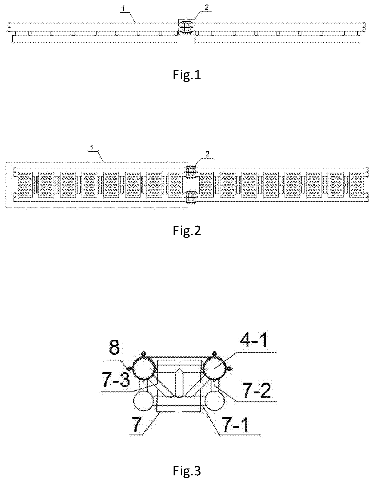
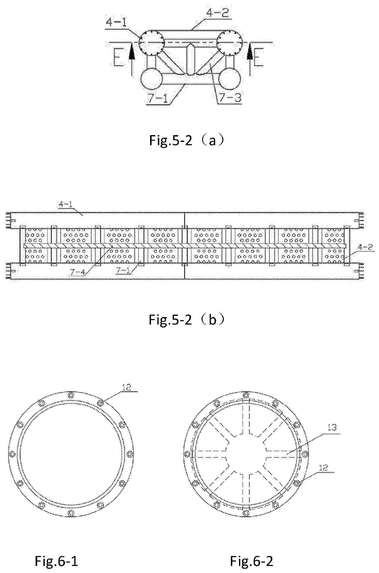
[0042]As shown in FIGS. 1, 2 and 4, an airbag-type floating breakwater of the present invention includes a plurality of water wave absorbing structure units 1 arranged along a length direction of the breakwater. The adjacent water wave absorbing structure units 1 are connected by a connecting unit 2. Mooring systems 3 can be symmetrically disposed on both sides of the water wave absorbing structure unit 1. The water wave absorbing structure units 1 can be integrated by the elastic connection of the connecting unit 2 and the limiting action with the mooring systems 3, so as to perform overall motion in wave to resist against the wave, as shown in FIG. 10-2.

[0043]The water wave absorbing structure unit 1 includes at least two floats arranged side by side and a wave absorbing plate 4-2 located on the floats, and the connecting unit 2 includes bases located ...


PUM


Abstract

The present invention discloses a quickly-detachable airbag-type floating breakwater, including a plurality of water wave absorbing structure units arranged along a length direction of the breakwater. The adjacent water wave absorbing structure units are connected by a connecting unit. The water wave absorbing structure unit comprises at least two floats arranged side by side and a wave absorbing plate located between the floats. The water wave absorbing structure unit comprises at least two floats arranged side by side and a wave absorbing plate located on the floats. The connecting unit comprises bases located at the ends of the floats, an airbag located between the adjacent bases, and a steel chain, the adjacent bases wrapping the airbag to form a buffer connecting structure. Adjacent water wave absorbing structure units can be quickly and conveniently assembled by a connecting unit, thereby simplifying the difficulty in a breakwater building and construction installation process, improving the post-maintenance convenience of the breakwater, and reducing the post-maintenance cost. The connecting unit adopting a buffer connecting structure formed by wrapping the airbag with the bases can effectively alleviate movement, extrusion and torsion between adjacent breakwaters.

Description

CROSS-REFERENCE TO RELATED APPLICATION[0001]This application claims the priority benefit of China application serial no. 201810776832.0, filed on Jul. 16, 2018. The entirety of the above-mentioned patent application is hereby incorporated by reference herein and made a part of this specification.BACKGROUNDTechnical Field[0002]The present invention relates to a breakwater, particularly relates to a quickly-detachable airbag-type floating breakwater, and belongs to the field of breakwaters.Background Art[0003]A breakwater system is one of important technical measures for guaranteeing offshore and ocean platform safety operations. For ocean structures, a breakwater can be protected by attenuating wave energy in a manner of reflecting wave, destroying wave water particle motion, performing resonance or the like, so as to provide a relatively steady ocean environment for the ocean structures, thereby improving the working efficiency and safety thereof, and reducing the economic loss. For...

Claims


Application Information

Patent Timeline
Patent Type & Authority Applications(United States)
IPC IPC(8): E02B3/06E02B3/16
CPCE02B3/16E02B3/062Y02A10/11
Inventor JI, CHUNYANCUI, JIELI, ZICHAOGUO, JIANTINGHUO, FALIZHOU, TAORANLIU, HUI
Owner JIANGSU UNIV OF SCI & TECH
Learn More