Electric Light Radiant Energy Control Systems

a technology of radiant energy control and electric light, which is applied in the direction of water installations, disinfection, construction, etc., can solve problems such as not always feasibl

Inactive Publication Date: 2020-01-16
VYV INC
View PDF0 Cites 9 Cited by
  • Summary
  • Abstract
  • Description
  • Claims
  • Application Information

AI Technical Summary

Problems solved by technology

UV systems include remote controlled robots and lockable rooms, which can only be used when a room is not occupied, which is not always feasible.

Method used


Image

  • Electric Light Radiant Energy Control Systems
  • Electric Light Radiant Energy Control Systems
  • Electric Light Radiant Energy Control Systems

Examples


Embodiment Construction

[0024]As an initial matter, in order to clearly describe the current disclosure it will become necessary to select certain terminology when referring to and describing relevant components within the disclosure. When doing this, if possible, common industry terminology will be used and employed in a manner consistent with its accepted meaning. Unless otherwise stated, such terminology should be given a broad interpretation consistent with the context of the present application and the scope of the appended claims. Those of ordinary skill in the art will appreciate that often a particular component may be referred to using several different or overlapping terms. What may be described herein as being a single part may include and be referenced in another context as consisting of multiple components. Alternatively, what may be described herein as including multiple components may be referred to elsewhere as a single part.

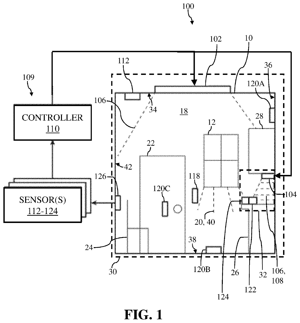
[0025]As indicated above, the disclosure relates generally to illu...


PUM

PropertyMeasurementUnit
wavelength rangeaaaaaaaaaa
energyaaaaaaaaaa

Abstract

Radiant energy control systems, methods, and apparatuses are provided. An example light emitting device may comprise a sensor operable to detect whether a space is occupied, and a controller in communication with the sensor and operable to cause output, via a first light emitter for a first time period in the space, of a white light comprising a spectral energy of up to 30% energy in a wavelength range of 380 to 420 nm, cause output, via a second light emitter for a second time period in the space, of a non-white light comprising a spectral energy greater than 70% energy in the wavelength range of 380 to 420 nm, and switch, based on whether the space is occupied and to achieve a minimum dosage of light in the wavelength range of 380 to 420 nm during a third period that includes the first time period and the second time period, between causing output of the white light and causing output of the non-white light.

Description

CROSS-REFERENCE TO RELATED APPLICATIONS[0001]This patent is a continuation of U.S. application Ser. No. 15 / 857,128, filed Dec. 28, 2017, which is a continuation-in-part of U.S. application Ser. No. 15 / 856,971, filed Dec. 28, 2017, and claims the benefit of U.S. Provisional Application No. 62 / 440,208, filed Dec. 29, 2016. U.S. application Ser. No. 15 / 857,128, U.S. application Ser. No. 15 / 856,971, and U.S. Provisional Application No. 62 / 440,208 are hereby incorporated by reference herein.TECHNICAL FIELD[0002]Aspects of the present disclosure generally relate to electric light systems, methods, and apparatus for using, generating, controlling or detecting radiant energy. Aspects of the present disclosure relate to controlling electric light sources that emit radiation in at least the near-ultraviolet portion of the light spectrum.BACKGROUND OF THE INVENTION[0003]The disclosure relates generally to illumination, and more particularly, to control systems for a disinfecting light emitting...

Claims


Application Information

Patent Timeline
Patent Type & Authority Applications(United States)
IPC IPC(8): A61L2/24A61L2/08A61L2/10A61L9/20A61L2/28
CPCA61L12/063A61L2202/25A61L2/0052A61L2202/11A61L2209/111A61L2/0047A61L2/24A61L2/10A61L2/084A61L2/28G01N31/226A61L2202/14A61L9/20
Inventor LALICKI, JORELBARRON, ROBERTWINSLOW, CORI JOSLYNWANG, YICHUAN
Owner VYV INC
Why Eureka
Try Eureka