
Lining Element, and Process for Manufacturing a Lining Element

Pending Publication Date: 2020-01-09
BAYERISCHE MOTOREN WERKE AG
View PDF4 Cites 0 Cited by
  • Summary
  • Abstract
  • Description
  • Claims
  • Application Information

AI Technical Summary

Benefits of technology

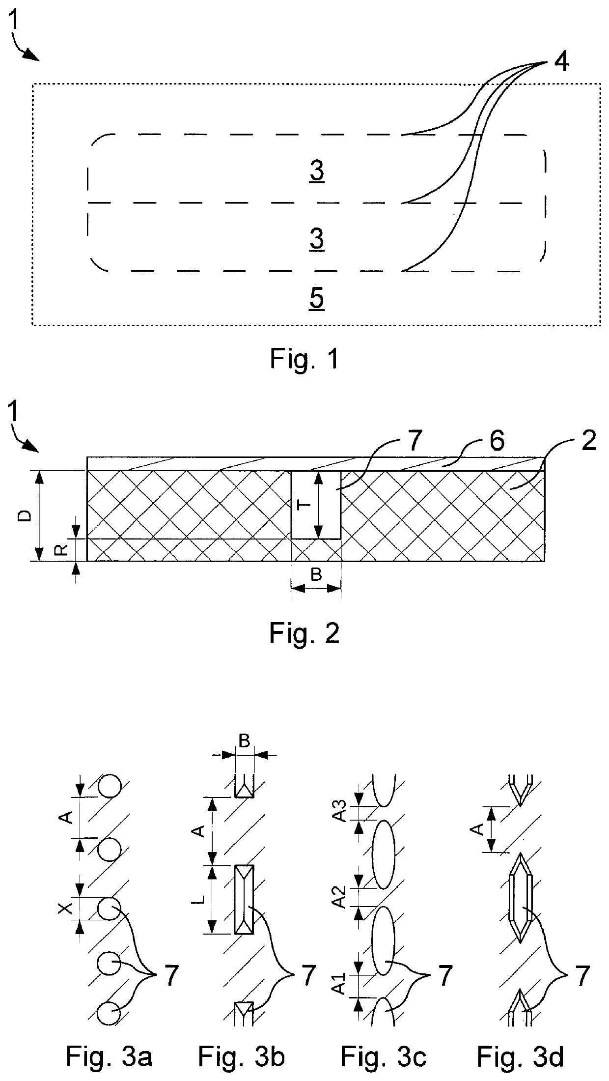
[0013]Furthermore, an embodiment is of advantage, in which the recesses are 1 mm to 4 mm deep, 1 mm to 3 mm wide, 1 mm to 10 mm long and/or are spaced by a distance A of 1 mm to 4 mm and/or the backing layer is 2 mm to 6 mm thick. In a cylindrical shape, the length L corresponds to the width B as diameter X. The distance between two recesses of a multiplicity of predetermined breaking points or the distance between the recess and a further recess should in each case be measured from an edge region or a side surface in the direction of the

Problems solved by technology

Methods following the production of the lining element are expensive and time-consuming because of additional machines, working steps, storage costs and handling and maintenance times. In the case of methods which are used integrally during the production of the lining element, the weakening of the lining element frequently stands out by means of a predetermined breaking contour on a visible side which face

Method used


Image

  • Lining Element, and Process for Manufacturing a Lining Element
  • Lining Element, and Process for Manufacturing a Lining Element

Examples


Example

DETAILED DESCRIPTION OF THE DRAWINGS

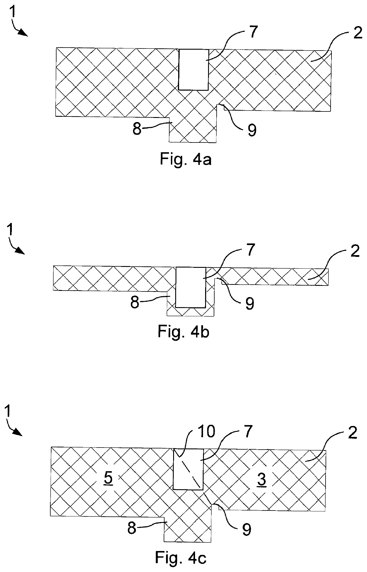
[0028]The figures are shown schematically by way of example. The same reference signs in the figures indicate identical functional and / or structural features.

[0029]FIG. 1 shows a lining element 1 with two predetermined breaking regions 3. The predetermined breaking regions 3 are each delimited by four predetermined breaking lines 4, wherein one predetermined breaking line 4 lies between the predetermined breaking regions 3 and delimits the two predetermined breaking regions 3 from each other such that a total of seven predetermined breaking lines 4 run on the lining element 1. The predetermined breaking lines 4 of the predetermined breaking regions 3 that provide a delimitation with respect to the surrounding region 5 merge into one another such that the corners of the predetermined breaking regions 3 are rounded with respect to the surrounding region 5. The individual predetermined breaking points are arranged along the respective predetermined b...


PUM

PropertyMeasurementUnit
Lengthaaaaaaaaaa
Lengthaaaaaaaaaa
Lengthaaaaaaaaaa

Abstract

A lining element for use in a vehicle in order to cover an airbag includes a dimensionally stable backing layer with a first predetermined breaking region which is delimited from a surrounding region and/or from a second predetermined breaking region by at least one predetermined breaking line, where a plurality of regularly spaced predetermined breaking points are disposed along the predetermined breaking line.

Description

CROSS REFERENCE TO RELATED APPLICATIONS[0001]This application is a continuation of PCT International Application No. PCT / EP2018 / 056532, filed Mar. 15, 2018, which claims priority under 35 U.S.C. § 119 from German Patent Application No. 10 2017 204 963.4, filed Mar. 23, 2017, the entire disclosures of which are herein expressly incorporated by reference.BACKGROUND AND SUMMARY OF THE INVENTION[0002]The invention relates to a lining element for use on a vehicle for covering an airbag.[0003]During the production of a vehicle, airbags are covered with lining elements for safety reasons and in order to improve the design. So that the airbag functions if triggered, the lining elements are designed in such a manner that they easily break or easily tear at predefined breaking points in comparison to the other regions of the lining element and allow the airbag to pass. The airbag penetrates or breaks through the lining elements in a previously defined predetermined breaking region. A predeter...

Claims


Application Information

Patent Timeline
IPC IPC(8): B60R21/2165B29C44/14B29C44/42B29C37/00B32B9/02B32B5/20
CPCB32B9/025B60R21/2165B29C44/146B29C44/428B29L2031/3038B32B2605/003B32B2262/101B32B5/20B29C37/0057B32B2266/025B60R21/237B29K2711/08B29K2023/12B29K2509/08B29K2995/0094B29K2995/0097B29C44/582B29C44/586B29L2009/00B29K2105/12B29C69/02B29D99/005
Inventor SCHWABL, MARTIN
Owner BAYERISCHE MOTOREN WERKE AG
Learn More