
Electronic Control Device

a control device and electronic technology, applied in the direction of relays, electrical apparatus construction details, casings/cabinets/drawers, etc., can solve the problems of contact parts prone to antecedent temperature drop, contact parts subject to sudden temperature drop, dew condensation, etc., and achieve the effect of suppressing dew condensation

Active Publication Date: 2020-01-02
HITACHI ASTEMO LTD
View PDF0 Cites 3 Cited by
  • Summary
  • Abstract
  • Description
  • Claims
  • Application Information

AI Technical Summary

Benefits of technology

The present invention provides a thermal mass element that helps to prevent a drop in temperature of a contact part when the connector terminal is cooled by outside air after a stop of device operation. This prevents dew condensation from occurring at the contact part inside a relay case.

Problems solved by technology

When an electronic control device whose relay is electrically connected to a connector terminal via a wiring route such as a bus bar is used in an extremely cold area, the connector terminal is cooled by outside air after a stop of device operation, and draws heat from a contact part of the relay, and causes the contact part to undergo a sudden drop in temperature.
Thus, even in a configuration that a relay case is partially cooled as in Patent Document 1 or 2, a contact part is liable to antecedently drop in temperature and undergo dew condensation.

Method used


Image

  • Electronic Control Device
  • Electronic Control Device
  • Electronic Control Device

Examples


first embodiment

[0027]The following describes an electronic control device of an electric brake booster according to the present invention in detail with reference to the drawings.

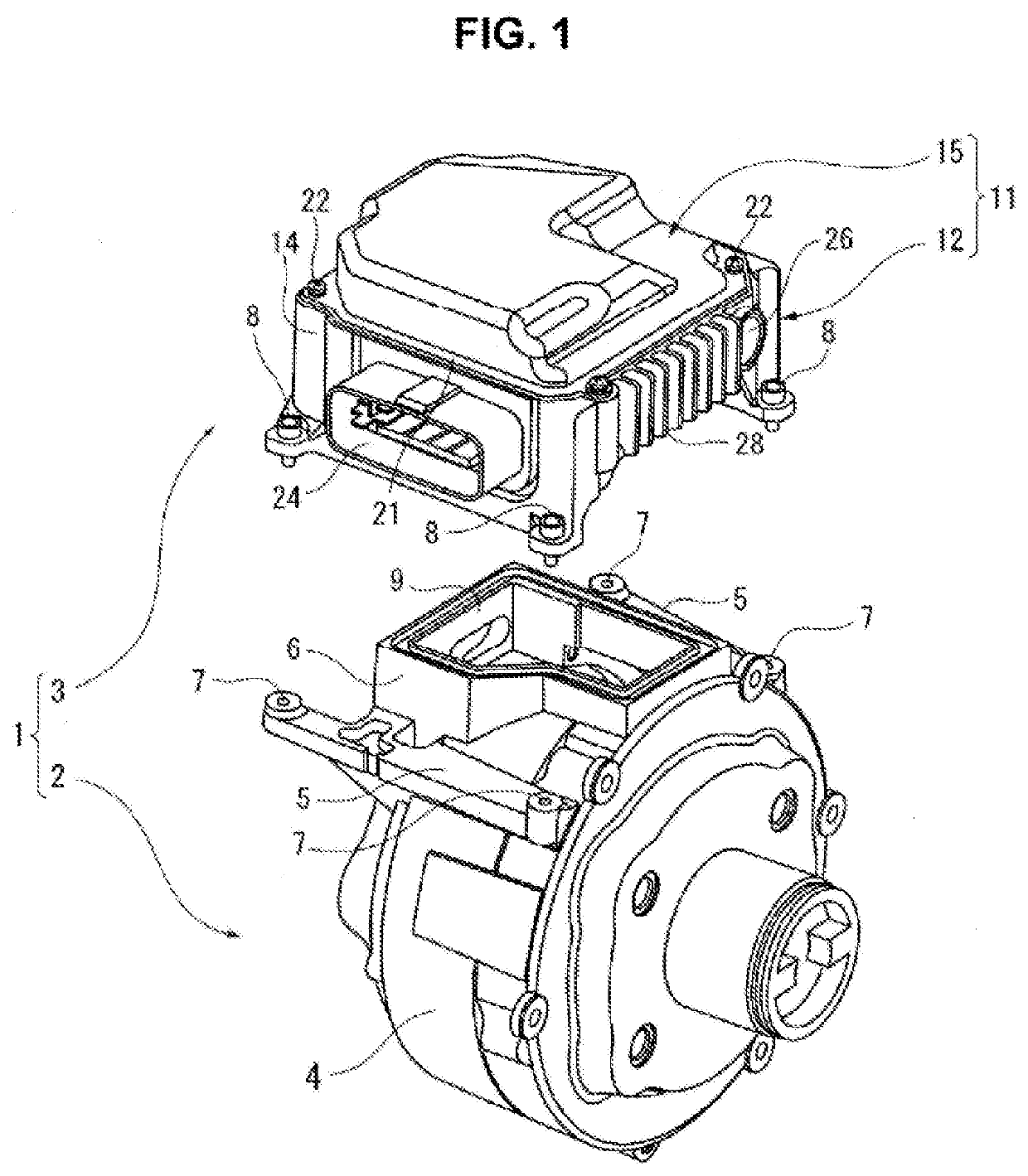
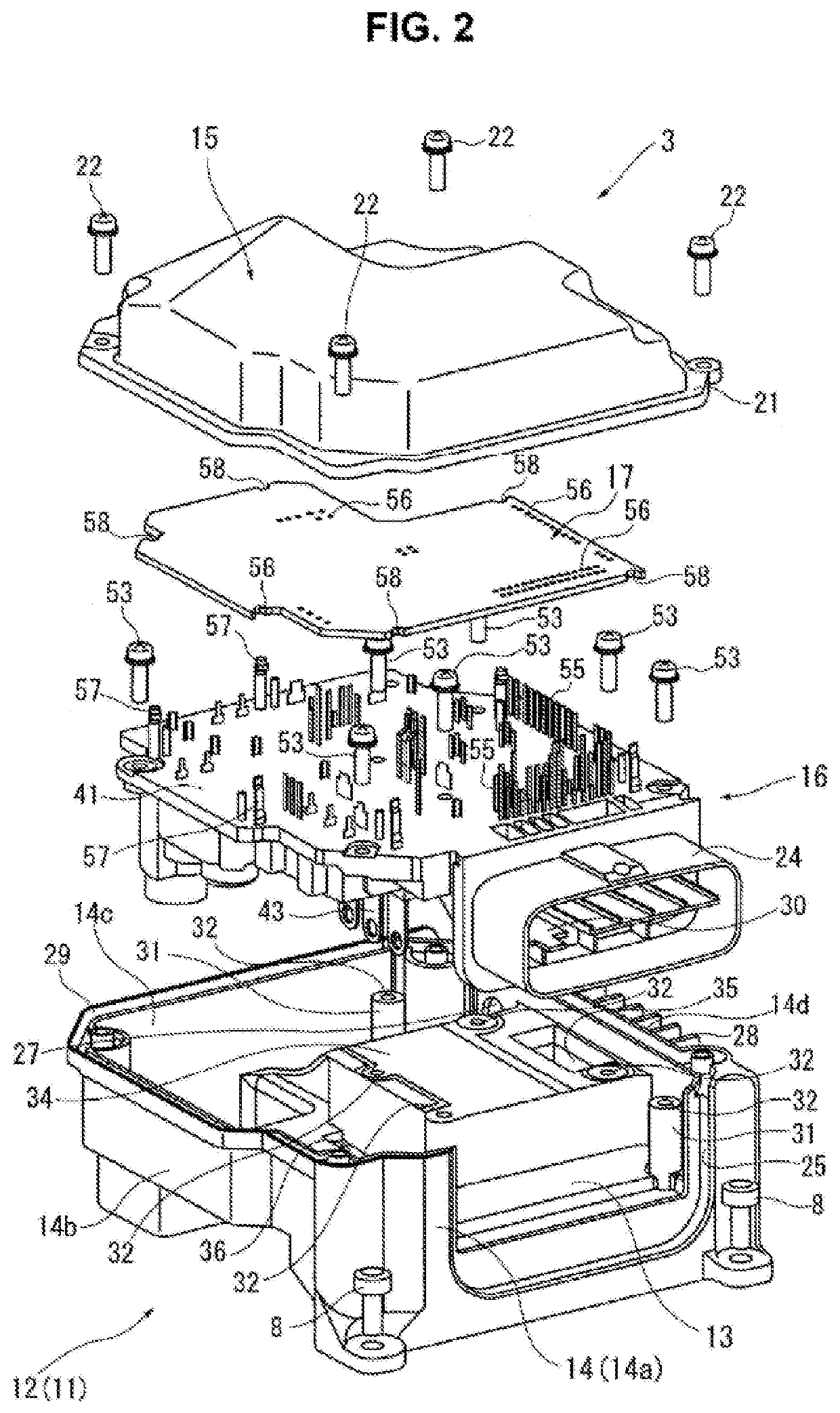
[0028]FIG. 1 is an exploded perspective view of an electric brake booster 1 including a motor control device 3, wherein motor control device 3 corresponds to the electronic control device according to the present invention. FIG. 2 is an exploded perspective view of motor control device 3.

[0029]Electric brake booster 1 shown in FIG. 1 is mounted to an engine room side of a dash panel not shown, the dash panel serving as a partition between an engine room and a vehicle interior of an automotive vehicle, and forms a booster mechanism for driving a master cylinder not shown in response to depression of a brake pedal mounted to a vehicle interior side of the dash panel. Electric brake booster 1 includes an electric motor 2 and motor control device 3, wherein: electric motor 2 drives a piston not shown of the master cylinder in...

case 91

[0065]Although relay case 91 of each relay 51 has a sealed structure, relay case 91 allows moisture around it to permeate inside it because relay case 91 is formed of a synthetic resin having moisture-permeability. For example, in a case of an extremely cold area reachable to 20° C. below the freezing point, while the vehicle is being driven (i.e. during operation of motor control device 3), an internal temperature of housing 11 of motor control device 3 is around 0° C. to 5° C. and moisture inside relay case 91 is thereby in a gaseous state. However, after the driving of the vehicle has been ended and the power supply of motor control device 3 has been shut off, a temperature of contact part 98 drops below the freezing point wherein contact part 98 is thermally connected to outside air via the metallic components such as the connector terminal (main-power-supply connector terminal 30) and bus bars 40 of power module 16, and thereby the gaseous moisture inside relay case 91 is liabl...


PUM


Abstract

An electronic control device includes a relay including a relay case and an electromagnet and a contact part. The relay case is structured to contain the electromagnet and the contact part. The contact part is structured to be opened and closed by action of the electromagnet. A connector terminal is electrically connected to the relay. A circuit board is structured to mount the relay and the connector terminal thereon. An exterior shell is structured to contain the circuit board such that the connector terminal is exposed outside the exterior shell. A thermal mass element is disposed in a wiring route between the relay and the connector terminal.

Description

TECHNICAL FIELD[0001]The present invention relates to an electronic control device including an electromagnetic relay.BACKGROUND ART[0002]Patent Document 1 discloses a relay that includes a relay case containing an electromagnet and a contact part, wherein the relay case is configured to form heat radiation panels at its ceiling apart from the contact part in order to suppress dew condensation from occurring at the contact part. This configuration sets the ceiling of the relay case lower in temperature than a vicinity of the contact part, and thereby makes moisture inside the relay case condense at the ceiling instead of the contact part.[0003]Patent Documents 2 discloses, as a conventional art, a relay configured such that a top face of a relay case is in contact with a chassis of a vehicle via a thermal conductive sheet for outwardly radiating heat generated inside the relay while the relay is ON.[0004]When an electronic control device whose relay is electrically connected to a co...

Claims


Application Information

Patent Timeline
IPC IPC(8): H05K7/14H01H45/04H01H45/12H01H50/12H02K11/33H05K5/00H05K7/20H02G3/16
CPCH01H2239/036H01H45/12H01H50/12H05K7/1432H01H45/04H02G3/16H05K5/006H02K11/33H05K7/20845H02K5/225H02K2211/03H02K5/18H01H50/04H02K9/223H05K7/14322
Inventor KUROIWA, NOBUYUKISAITO, HIROYUKINAKANO, KAZUHIKO
Owner HITACHI ASTEMO LTD
Learn More