High-frequency module and communication device
a communication device and high-frequency technology, applied in the field of high-frequency modules and communication devices, can solve the problems of deterioration of isolation characteristics between the switch unit and the amplifying unit, and achieve the effect of improving isolation characteristics and improving isolation characteristics
- Summary
- Abstract
- Description
- Claims
- Application Information
AI Technical Summary
Benefits of technology
Problems solved by technology
Method used
Image

Examples
first embodiment
1. Circuit Configuration of High-frequency Module
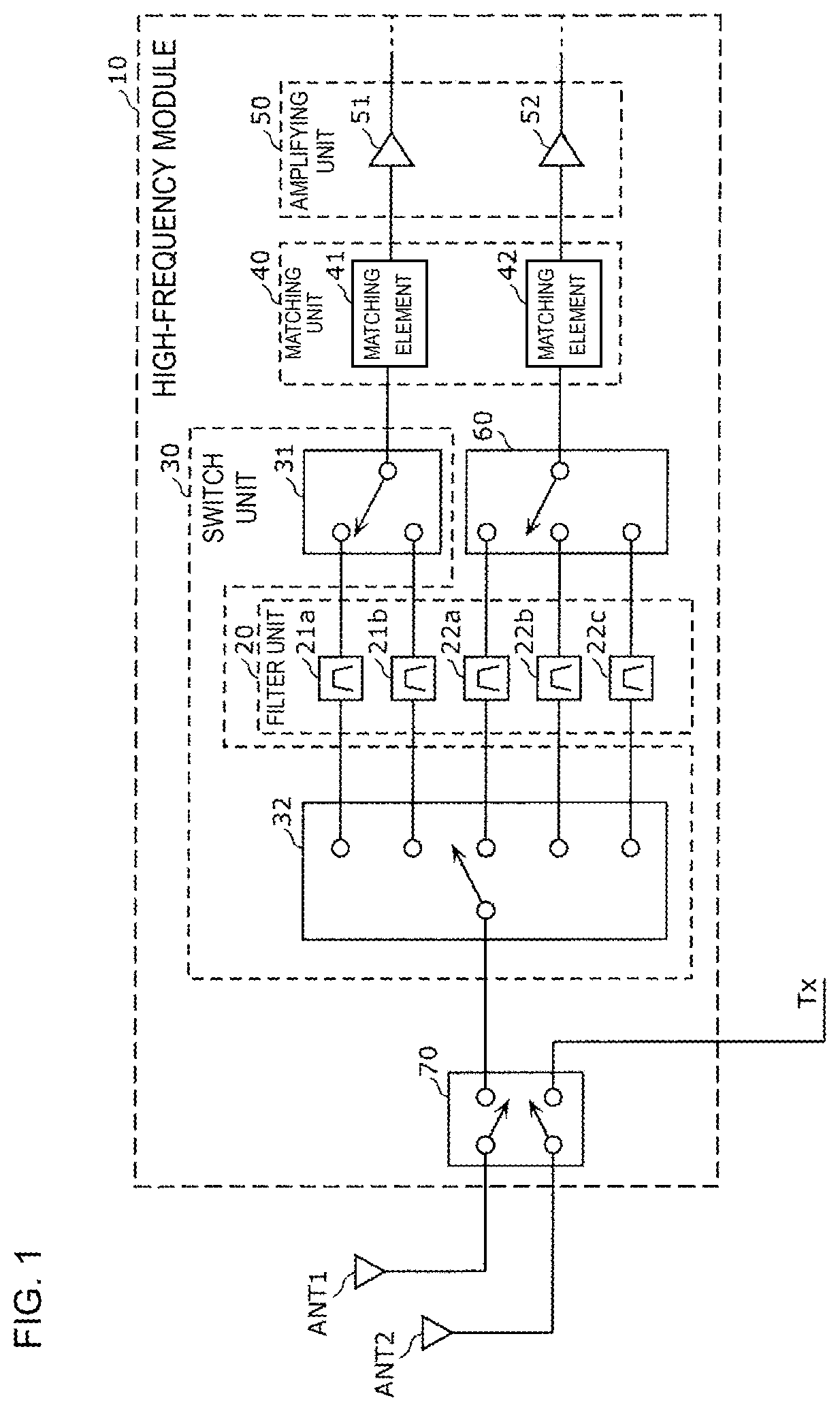
[0040]FIG. 1 is a circuit configuration diagram illustrating an example of a high-frequency module 10 according to the first embodiment. In FIG. 1, antenna elements ANT1 and ANT2 are illustrated in addition to the high-frequency module 10. The antenna elements ANT1 and ANT2 are multiband compatible antennas that are compliant with a communication standard, such as long term evolution (LTE), for transmitting or receiving high-frequency signals.
[0041]The high-frequency module 10 is, for example, a module disposed in a front end unit included in a multi-mode / multiband compatible cellular phone. The high-frequency module 10 is built in a multiband compatible cellular phone compliant with a communication standard such as LTE.
[0042]The high-frequency module 10 includes a filter unit 20 including a plurality of filters, a switch unit 30 connected to the filter unit 20, an amplifying unit 50 configured to amplify a high-frequency signal passi...
second embodiment
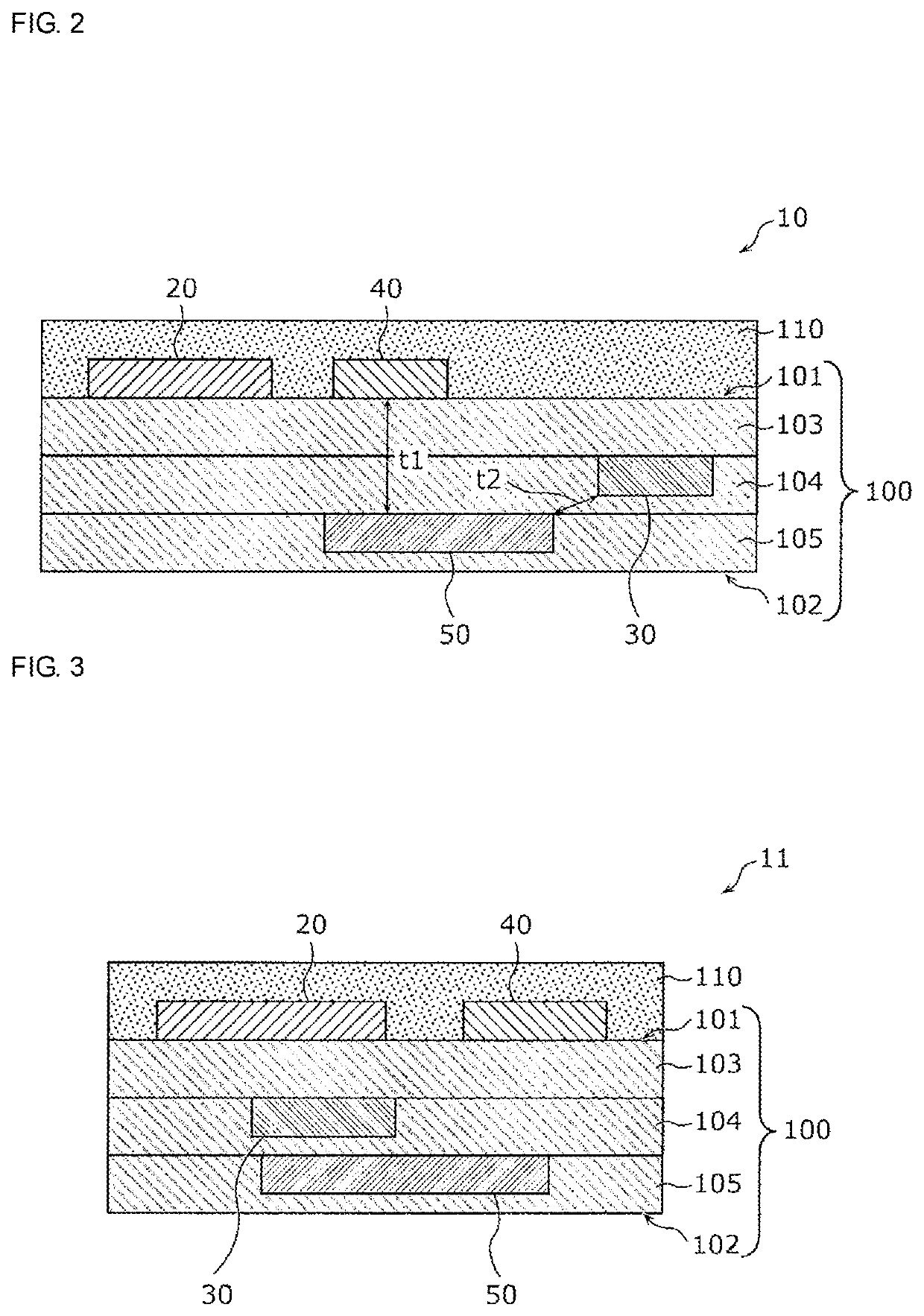
[0062]The second embodiment will be described with reference to FIG. 3. Since a circuit configuration of a high-frequency module 11 according to the second embodiment is the same as that of the high-frequency module 10 according to the first embodiment, a description thereof will be omitted.
[0063]FIG. 3 is a cross-sectional view illustrating an example of the high-frequency module 11 according to the second embodiment. In FIG. 3, the illustration of the second switch 60 and the fourth switch 70 is omitted. A structure of the high-frequency module 11 according to the second embodiment is different from that of the high-frequency module 10 according to the first embodiment in that at least a part of the switch unit 30 and at least a part of the amplifying unit 50 overlap with each other in a plan view of the multilayer substrate 100. The other points are the same as those of the high-frequency module 10 according to the first embodiment. When a shape of the switch unit 30 in a plan vi...
third embodiment
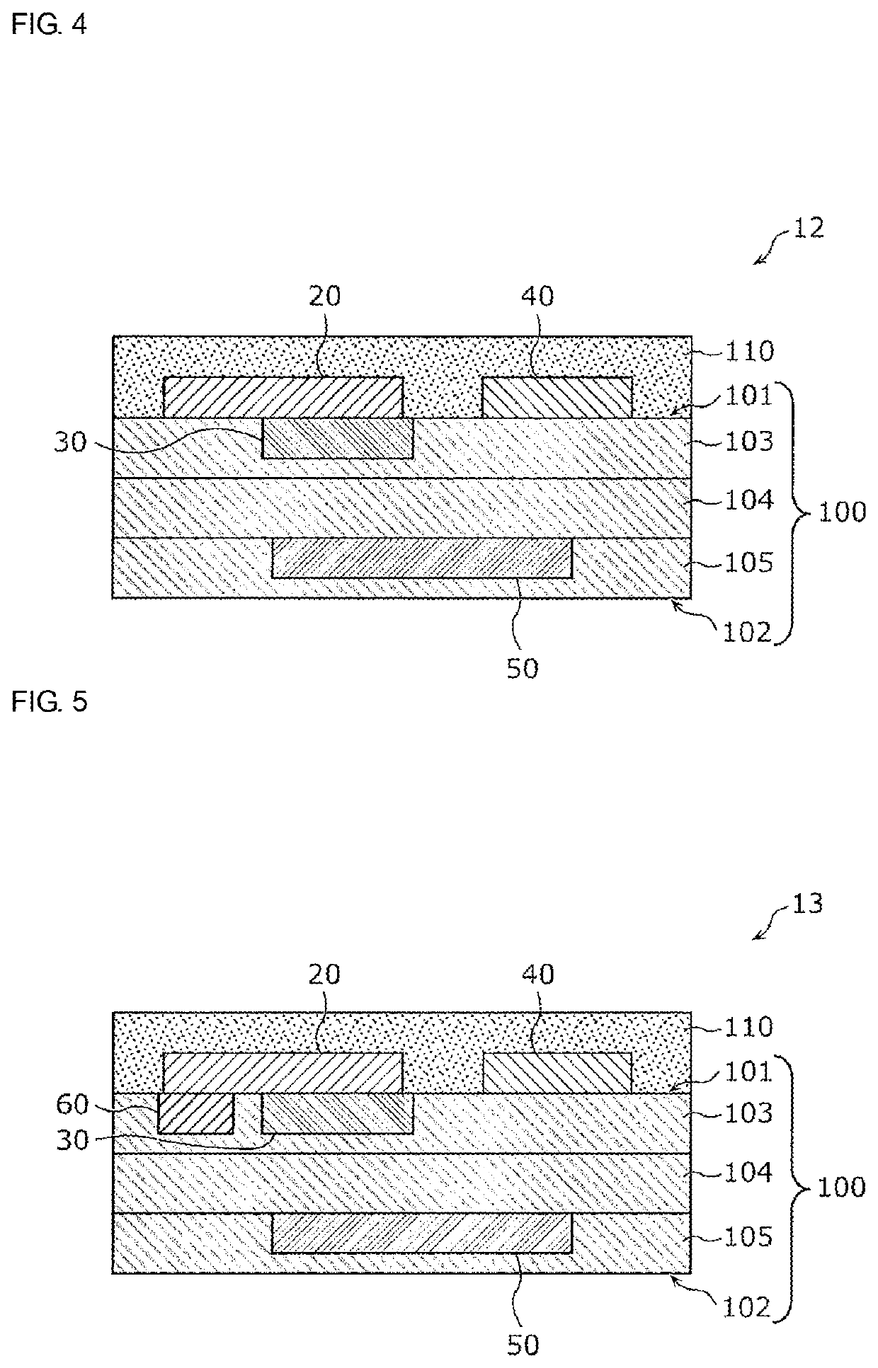
[0066]The third embodiment will be described with reference to FIG. 4. Since a circuit configuration of a high-frequency module 12 according to the third embodiment is the same as that of the high-frequency module 10 according to the first embodiment, a description thereof will be omitted.
[0067]FIG. 4 is a cross-sectional view illustrating an example of the high-frequency module 12 according to the third embodiment. In FIG. 4, the illustration of the second switch 60 and the fourth switch 70 is omitted. A structure of the high-frequency module 12 according to the third embodiment is different from that of the high-frequency module 11 according to the second embodiment in that the switch unit 30 is provided in or on a layer (for example, the inner layer 103) on the side of the one main surface 101 among the plurality of layers configuring the multilayer substrate 100. The other points are the same as those of the high-frequency module 11 according to the second embodiment. Note that ...
PUM
 Abstract
Description
Claims
Application Information
 - R&D
- Intellectual Property
- Life Sciences
- Materials
- Tech Scout
- Unparalleled Data Quality
- Higher Quality Content
- 60% Fewer Hallucinations
Browse by: Latest US Patents, China's latest patents, Technical Efficacy Thesaurus, Application Domain, Technology Topic, Popular Technical Reports.
© 2025 PatSnap. All rights reserved.Legal|Privacy policy|Modern Slavery Act Transparency Statement|Sitemap|About US| Contact US: help@patsnap.com