Head-mounted display apparatus

a display apparatus and head-mounted technology, applied in the field of head-mounted display apparatuses, can solve problems such as image quality reduction

Active Publication Date: 2020-01-02
SEIKO EPSON CORP
View PDF0 Cites 2 Cited by
  • Summary
  • Abstract
  • Description
  • Claims
  • Application Information

AI Technical Summary

Problems solved by technology

However, with such a cross dichroic prism, optically imperfect parts arise at a center of a bonded part of the triangular prisms.
Brightness dif

Method used


Image

  • Head-mounted display apparatus
  • Head-mounted display apparatus
  • Head-mounted display apparatus

Examples


exemplary embodiment 1

[0024]A head-mounted display apparatus according to this exemplary embodiment is an example of a head-mounted display used while worn on a user's head.

[0025]In the description below, the term “head-mounted display” is abbreviated “HMD”.

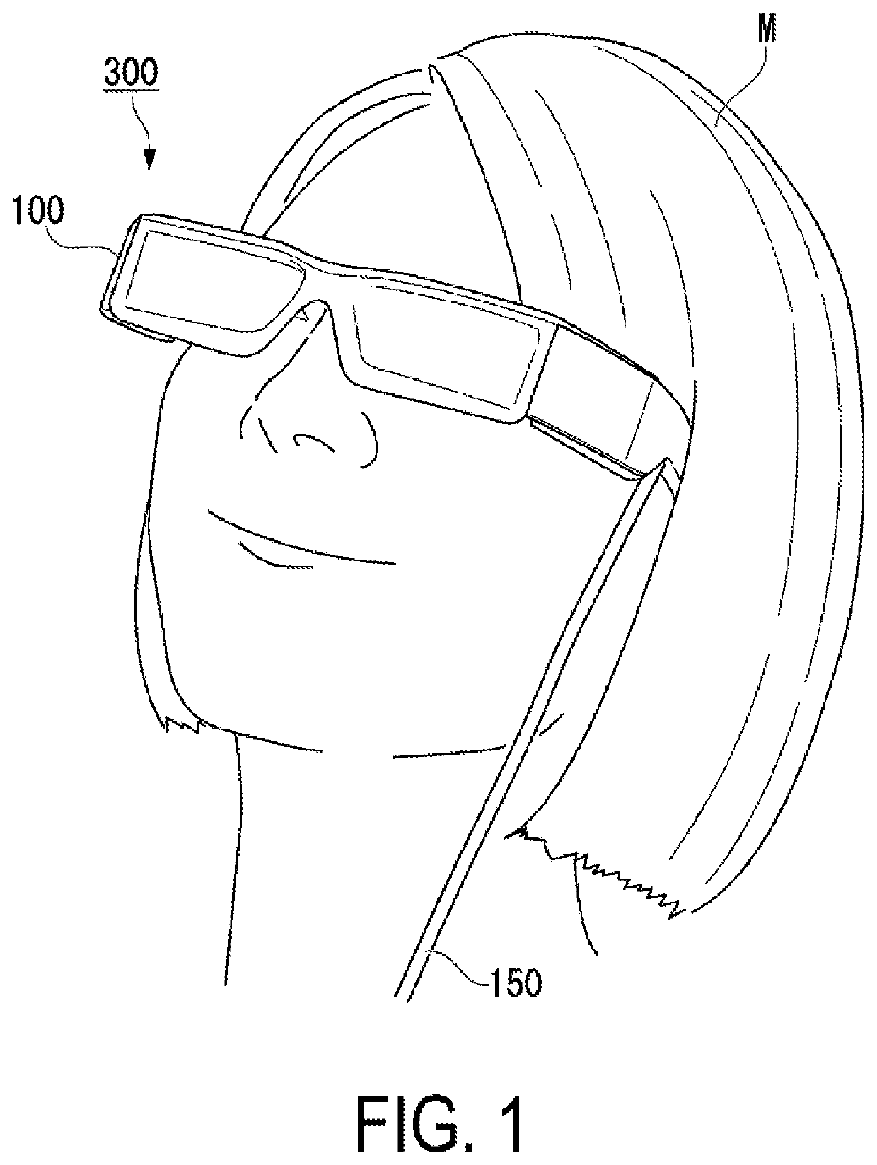
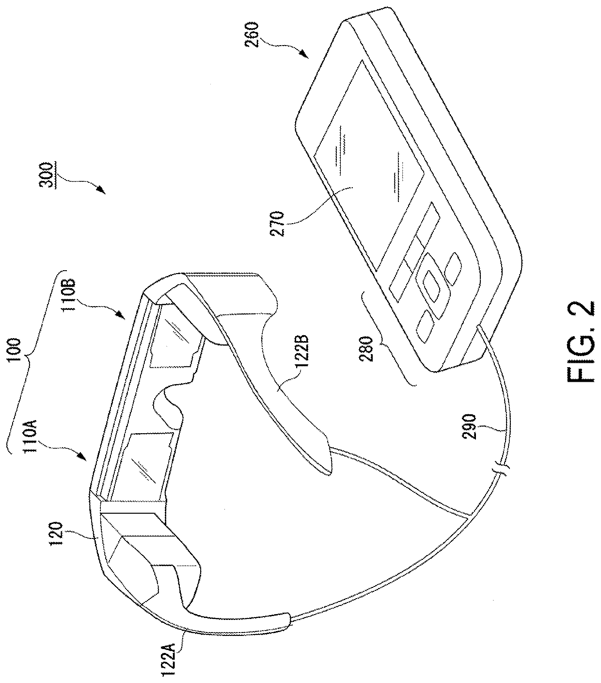
[0026]FIG. 1 is a diagram illustrating a user wearing an HMD according to this exemplary embodiment. FIG. 2 is a perspective view of the HMD according to this exemplary embodiment.

[0027]As illustrated in FIG. 1, a head-mounted display apparatus (HMD) 300 of this exemplary embodiment is used by being worn on the user's head as the user would wear eyeglasses. The HMD 300 of this exemplary embodiment is a non-transparent HMD that covers the user's eyes.

[0028]As illustrated in FIG. 2, the HMD 300 includes a display unit 100 having an eyeglasses-like shape, and a controller 260 small enough for the user to be able to hold the controller 260 in his or her hand. The display unit 100 and the controller 260 are communicatively coupled by a wire or wirelessly. ...

exemplary embodiment 2

[0094]For example, in the image generation unit 11 of the above exemplary embodiment, organic EL display elements are used as the first display panel 20, the second display panel 21, and the third display panel 22. In this case, the blue image light GB, the green image light GG, and the red image light GR emitted from the respective display panels are unpolarized light. As such, it is necessary to use films lacking polarized light separation functionality as the first dichroic film 61 and the second dichroic film 62. A dichroic film lacking polarized light separation functionality in this manner is relatively thick at 5 μm.

[0095]An image generation unit according to this exemplary embodiment differs from that in the above exemplary embodiment in that dichroic films having polarized light separation functionality are used as the first dichroic film and the second dichroic film.

[0096]FIG. 7 is a diagram schematically illustrating the configuration of an image generation unit according...


PUM


Abstract

A head-mounted display apparatus includes a cross dichroic prism including four triangular prisms that are mutually bonded, and a first dichroic film and a second dichroic film provided between adjacent prisms of the four triangular prisms, a plurality of display panels arranged respectively opposite to a plurality of light incident planes of the cross dichroic prism, and a projection optical system configured to project light emitted from the cross dichroic prism onto a pupil of a user. The cross dichroic prism includes an optically imperfect part at a center of a bonded part of the four triangular prisms. A ratio between an aerial conversion length from each of light-emission planes of the plurality of display panels to the center of the bonded part, and a width of the optically imperfect part, is greater than or equal to 250:1.

Description

[0001]The present application is based on, and claims priority from JP Application Serial Number 2018-124798, filed Jun. 29, 2018, the disclosure of which is hereby incorporated by reference herein in its entirety.BACKGROUND1. Technical Field[0002]The present disclosure relates to a head-mounted display apparatus.2. Related Art[0003]A head-mounted display apparatus such as a head-mounted display, which is used while worn on an observer's head, is known as a recent example of a wearable information device. To achieve a brighter color image display in such a head-mounted display apparatus, it is necessary to employ a method that synthesizes image light of each R, G, and B color, which are generated by three corresponding display devices. A cross dichroic prism such as that disclosed in JP-A-2007-78779 is known as a synthesizing optical system that synthesizes image light of each R, G, and B color. This cross dichroic prism includes four triangular prisms joined together by an adhesive...

Claims


Application Information

Patent Timeline
IPC IPC(8): G02B27/01G02B27/09
CPCG02B27/0176G02B27/0172G02B2027/0178G02B27/0972G02B2027/0114
Inventor YONEKUBO, MASATOSHIFUKASE, AKIO
Owner SEIKO EPSON CORP
Why Eureka
Try Eureka