Stationary Storage Device for Temporarily Storing Electric Energy in an Electric Supply Grid, Operating Method, and Retrofitting Module for the Stationary Storage Device

Active Publication Date: 2020-01-02
BAYERISCHE MOTOREN WERKE AG
View PDF0 Cites 6 Cited by
  • Summary
  • Abstract
  • Description
  • Claims
  • Application Information

AI Technical Summary

Benefits of technology

[0017]The invention has the advantage that, building on a stationary storage device with low componentry expense, a functionality of a charging column is expanded or added. Thanks to the combining of the charging station with the stationary storage device to form a technical unit, components can be utilized synergistically by combining the connection device for the motor vehicle and the at least one electrical storage unit at the DC side across the DC bus to form a unit, so that the electrical charging current can be transferred directly from a storage unit to the motor vehicle, bypassing an AC-DC conversion. In particular, during a charging process in which energy is transferred from at least one storage unit to the motor vehicle, no conversion step of a

Problems solved by technology

Since the number of electric vehicles in use and their technically possible charging power are constantly increasing, it is increasingly hard to provide these high powers at the charging columns for the stability and economic effectiveness of a supply grid.
But it is evident from FIG. 1 that a considerable number of electrical apparatuses is necessary for the supplying of the electric vehicle 13 with the desired electrical powe

Method used


Image

  • Stationary Storage Device for Temporarily Storing Electric Energy in an Electric Supply Grid, Operating Method, and Retrofitting Module for the Stationary Storage Device
  • Stationary Storage Device for Temporarily Storing Electric Energy in an Electric Supply Grid, Operating Method, and Retrofitting Module for the Stationary Storage Device
  • Stationary Storage Device for Temporarily Storing Electric Energy in an Electric Supply Grid, Operating Method, and Retrofitting Module for the Stationary Storage Device

Examples


Example

DETAILED DESCRIPTION OF THE DRAWINGS

[0038]In the figures, functionally equal elements are given the same reference numbers in order to demonstrate the functional equivalence of these elements.

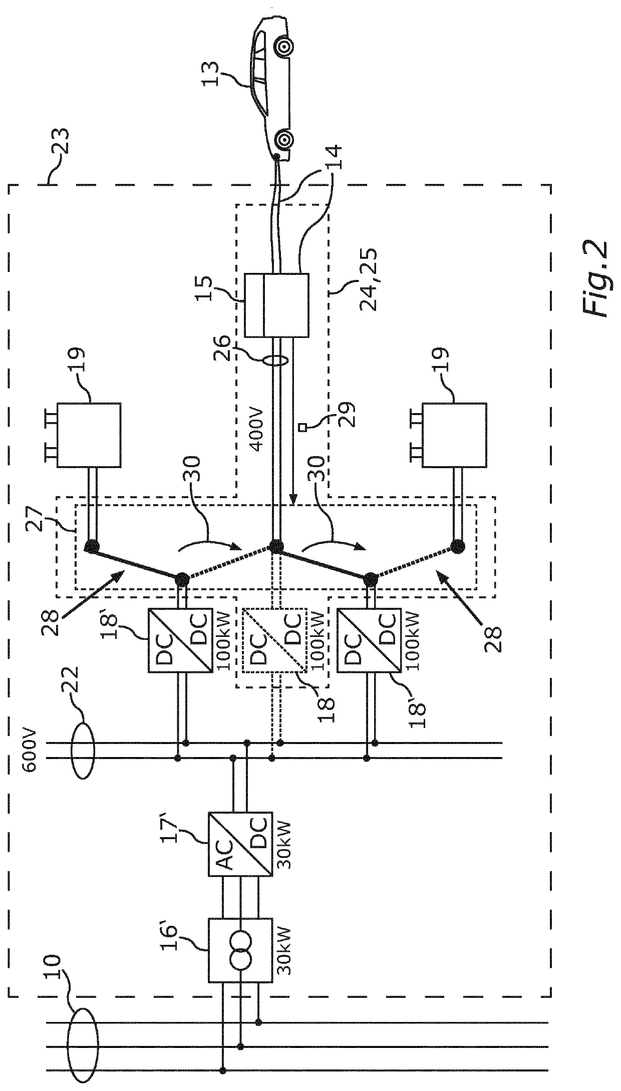
[0039]FIG. 2 shows a stationary storage device 23, which can be connected to a supply grid 10, which for example in the illustrated manner may comprise three phases with an effective voltage of 400 V, for example. For the buffering or temporary storing of electric energy, the stationary storage device 23 may comprise one or preferably more than one storage unit 19. A storage unit 19 may be formed, for example, on the basis of a battery or several batteries and / or a dual-layer capacitor or several dual-layer capacitors. Each storage unit 19 may be coupled across a DC-DC converter 18′ to a DC bus 22. The DC bus 22 may be formed for example on the basis of busbars and / or cables. In the DC bus 22, an electric voltage with constant sign may be provided. The DC bus 22 may be interconnected with the s...


PUM


Abstract

A stationary storage device configured to temporarily store electric energy in an electric supply grid includes at least one electric storage unit, each being connected to a common DC bus by a respective DC-DC converter. The storage device further includes a bidirectionally operated AC-DC converter for coupling the common DC bus to the supply grid, and a charging device configured to exchange energy with an electrically operated motor vehicle. The charging device includes a connection device configured to connect the electrically operated motor vehicle in order to exchange said energy, and a charge control device configured to control exchange of said energy. A coupling device is provided which is configured to electrically connect the connection device to the common DC bus via one or more DC-DC converters in order to exchange said energy.

Description

CROSS REFERENCE TO RELATED APPLICATIONS[0001]This application is a continuation of PCT International Application No. PCT / EP2018 / 055225, filed Mar. 2, 2018, which claims priority under 35 U.S.C. § 119 from German Patent Applications Nos. 10 2017 204 074.2, filed Mar. 13, 2017, and 10 2017 207 102.8, filed Apr. 27, 2017, the entire disclosures of which are herein expressly incorporated by reference.BACKGROUND AND SUMMARY OF THE INVENTION[0002]The invention relates to a stationary storage device for temporarily storing electric energy in an electric supply grid. The invention also relates to an operating method for operating such a stationary storage device and to a retrofitting module which can be installed in a conventional stationary storage device.[0003]A stationary storage device may be installed or connected e.g. in a supply grid close to an electrical consumer or electrical generator so as to be able to avoid electric energy having to be transported over long distances by the su...

Claims


Application Information

Patent Timeline
IPC IPC(8): B60L53/10H02J7/00B60L53/53B60L53/14
CPCB60L2210/30H02J3/32B60L53/11B60L2210/10H02J7/0027B60L53/14B60L53/53B60L53/63B60L53/66H02J7/342B60L50/60H02J7/02H02J2207/20Y02T90/16Y02T10/70Y02T90/14Y02T10/7072Y02T90/12Y04S10/126Y02E60/00H02J3/322H02J7/0013
Inventor GOHLA-NEUDECKER, BODOHESSELMANN, JANJURASCHEK, STEFANMOHR, SOERENPFEIFFER, ALBRECHT
Owner BAYERISCHE MOTOREN WERKE AG
Why Eureka
Try Eureka