Acoustic wave device, high frequency front end circuit, and communication apparatus
a high-frequency front end circuit and acoustic wave technology, applied in the direction of electrical devices, impedence networks, etc., can solve the problems of deterioration of the characteristics of the acoustic wave device, achieve effective reduction or prevention of high-order modes, reduce or prevent high-order modes, and achieve high acoustic velocity
- Summary
- Abstract
- Description
- Claims
- Application Information
AI Technical Summary
Benefits of technology
Problems solved by technology
Method used
Image
Examples
first preferred embodiment
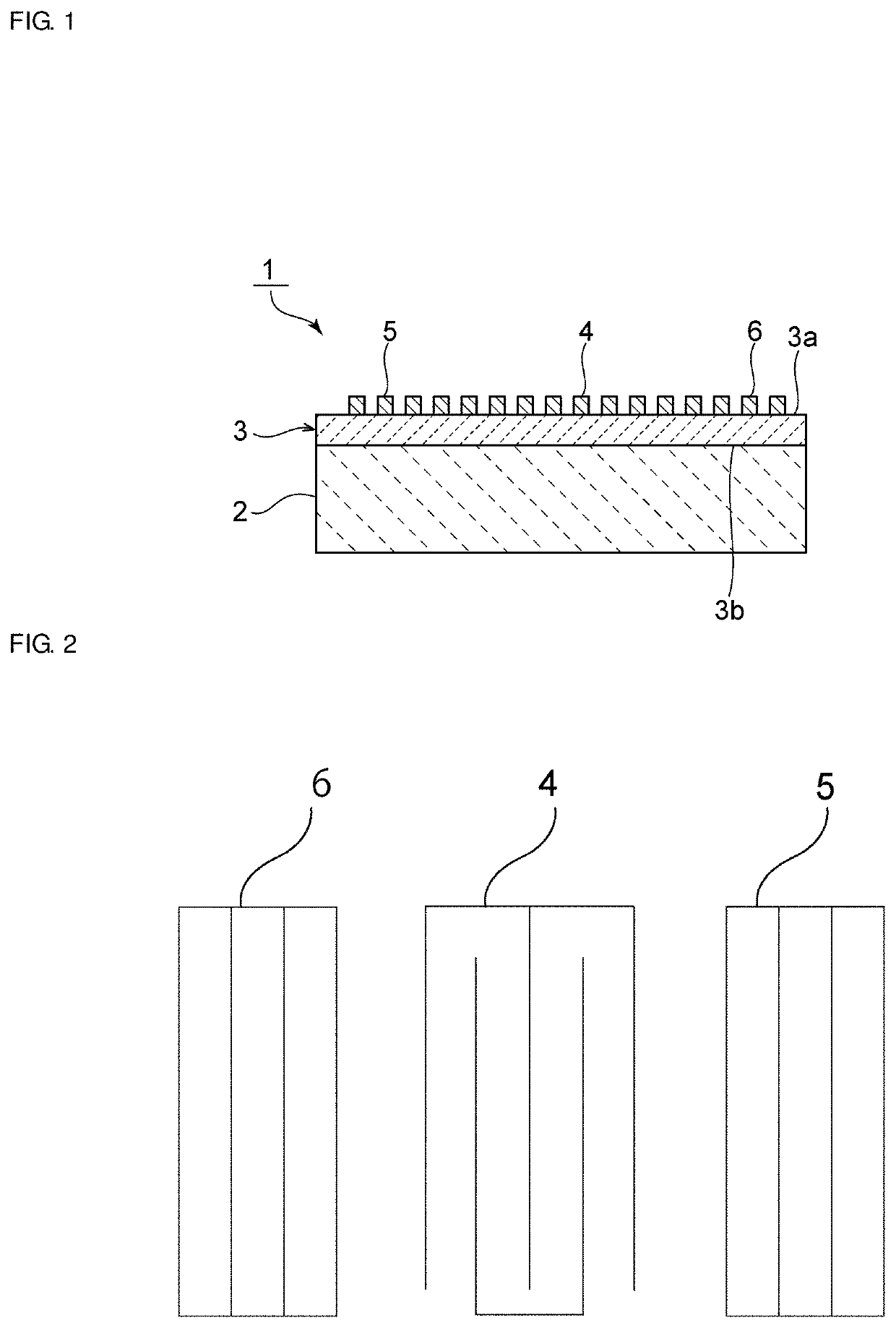
[0057]FIG. 1 is a front cross-sectional view of an acoustic wave device according to a first preferred embodiment of the present invention, and FIG. 2 is a schematic plan view illustrating an electrode structure of the acoustic wave device according to the first preferred embodiment.
[0058]An acoustic wave device 1 includes a material layer 2 made of a single crystal. Note that the material layer 2 is preferably a silicon (Si) single crystal, for example. A piezoelectric body 3 made of a single crystal is laminated on the material layer 2. The piezoelectric body 3 is preferably an Li2B4O7 single crystal, for example. In the present preferred embodiment, the material layer 2 also defines and functions a support substrate supporting the piezoelectric body 3.
[0059]The piezoelectric body 3 includes first and second principal surfaces 3a and 3b opposing each other. The piezoelectric body 3 is preferably directly laminated on the material layer 2 so that the second principal surface 3b con...
second preferred embodiment
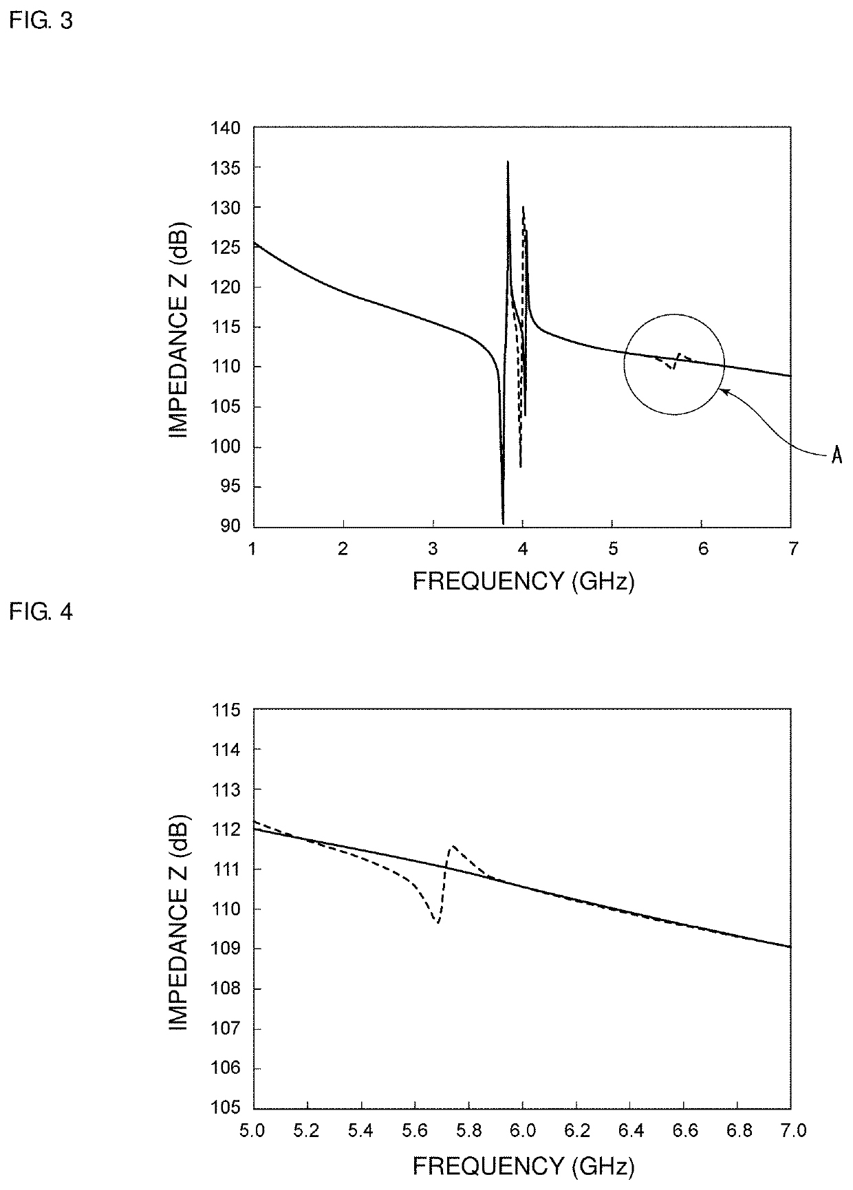
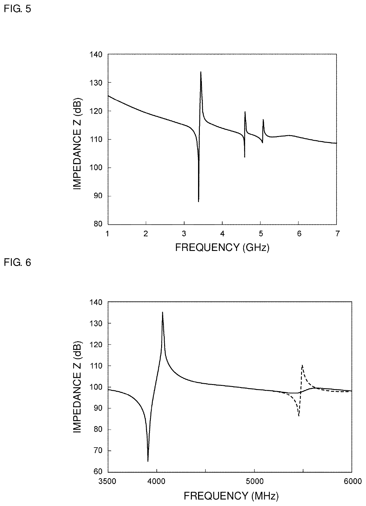
[0091]In a second preferred embodiment of the present invention, similarly to the first preferred embodiment, the piezoelectric body 3 made of a single crystal or a material close to a single crystal is laminated on the material layer 2 made of a single crystal or a material close to a single crystal. In other words, the piezoelectric body 3 which has Euler angles (φ2, θ2, ψ2) and whose elastic constant at the Euler angles (φ2, θ2, ψ2) is represented by Expression 1 is laminated on the material layer 2 which has Euler angles (φ1, θ1, ψ1) and whose elastic constant at the Euler angles (φ1, θ1, ψ1) is represented by Expression 1. Note that, in the second preferred embodiment, the piezoelectric body is preferably made of LiTaO3, a film thickness thereof is preferably about 0.30λ, and a Y cut-angle is preferably about 50°, for example. Accordingly, the Euler angles of LiTaO3 are determined to be (0°, 140°, 0°).
[0092]Other elements, that is, a material of an IDT electrode, a film thickne...
third preferred embodiment
[0120]In the third preferred embodiment, a material layer having an imaginary elastic constant in which only the value of an elastic constant C56(=C65) was varied with respect to the elastic constant in the case of Euler angles of a silicon single crystal being (−45°, −54.7°, 0°) was used. Other components are preferably the same or substantially the same as those in the second preferred embodiment.
[0121]In this case, the value of C56(=C65) was varied in various manners.
[0122]FIG. 11 is a graph showing a relationship between a magnitude of the elastic constant C56 and a phase maximum value of a high-order mode. When Euler angles of LiTaO3 are (0°, 140°, 0°), the elastic constant C56 is about −3.7 GPa, which is a negative value.
[0123]Therefore, when the elastic constant C56 of the silicon single crystal has a positive value, the high-order mode is able to be reduced or prevented. As shown in FIG. 11, in a region where the value of the elastic constant C56 of the silicon single crysta...
PUM
 Abstract
Description
Claims
Application Information
 - R&D
- Intellectual Property
- Life Sciences
- Materials
- Tech Scout
- Unparalleled Data Quality
- Higher Quality Content
- 60% Fewer Hallucinations
Browse by: Latest US Patents, China's latest patents, Technical Efficacy Thesaurus, Application Domain, Technology Topic, Popular Technical Reports.
© 2025 PatSnap. All rights reserved.Legal|Privacy policy|Modern Slavery Act Transparency Statement|Sitemap|About US| Contact US: help@patsnap.com


