Method for producing a biodigester reactor and membrane template

a biodigester and reactor technology, applied in the field of biodigester systems, can solve the problems of short-term degradation of pvc, increasing the implementation cost of biodigesters manufactured with pvc, and reducing efficiency

Active Publication Date: 2019-12-19
BUEN MANEJO DEL CAMPO S A DE
View PDF4 Cites 1 Cited by
  • Summary
  • Abstract
  • Description
  • Claims
  • Application Information

AI Technical Summary

Benefits of technology

The present invention is related to a modular reactor for biogas conversion. The invention provides a method for manufacturing a reactor by dividing a membrane template into segments corresponding to the body and ends of the reactor. This allows for easy adjustment of the reactor capacity by modifying the body segment template. The reactor system also includes a mixer coupled to a common fuel engine, which uses biogas as a fuel. The invention helps to make biogas compatible with the engine, allowing for direct injection and gas burning without the need for liquid fuel.

Problems solved by technology

However, PVC undergoes a short-term degradation as a result of said sunrays, so users cover the reactors, or create a sort of greenhouse for said reactors, thereby reducing the efficiency and increasing the implementation cost for biodigesters manufactured with PVC.
The reactor surface where said creases are located is subjected to a plurality of undesired efforts on the material, since said zones will eventually exhibit leakages or tears, thus reducing the reactor lifespan, and representing a risk to users.
Also, such creases may not be prevented even after the maximum inflation of the reactor, since this only increases the undesired efforts on the material, i.e. the creases remain, but said creases exert greater efforts on the material.
In this regard, it has been found that the biogas thus obtained cannot be directly used by a user, since this gas contains hydrogen sulfide, which is highly corrosive and has significant amounts of water.
However, this variation in the user's needs makes it difficult to manufacture a standardized biodigester system, since several square meters of membrane are needed to manufacture a standard biodigester system.
In this regard, it has been found that the users' needs change with time, and in certain cases this results in the user requiring to expand its biodigester system and also to expand the biodigester system capacities, including the land area required and the respective ditch.
However, the technique currently used for the manufacture of biodigester systems does not allow for such expansion.

Method used


Image

  • Method for producing a biodigester reactor and membrane template
  • Method for producing a biodigester reactor and membrane template
  • Method for producing a biodigester reactor and membrane template

Examples


Embodiment Construction

[0040]The following description is provided to enable those skilled in the art to make and use the embodiments, and said description is provided within the context of a particular application and the requirements thereof. Various modifications to the embodiments disclosed herein will become easily evident to those skilled in the art and the general principles defined herein may be applied to other embodiments and applications without departing from the spirit and scope of the present disclosure. Therefore, the present invention is not limited to the embodiments shown, but on the contrary, the present invention must conform to the widest scope consistent with the principles and characteristics disclosed herein.

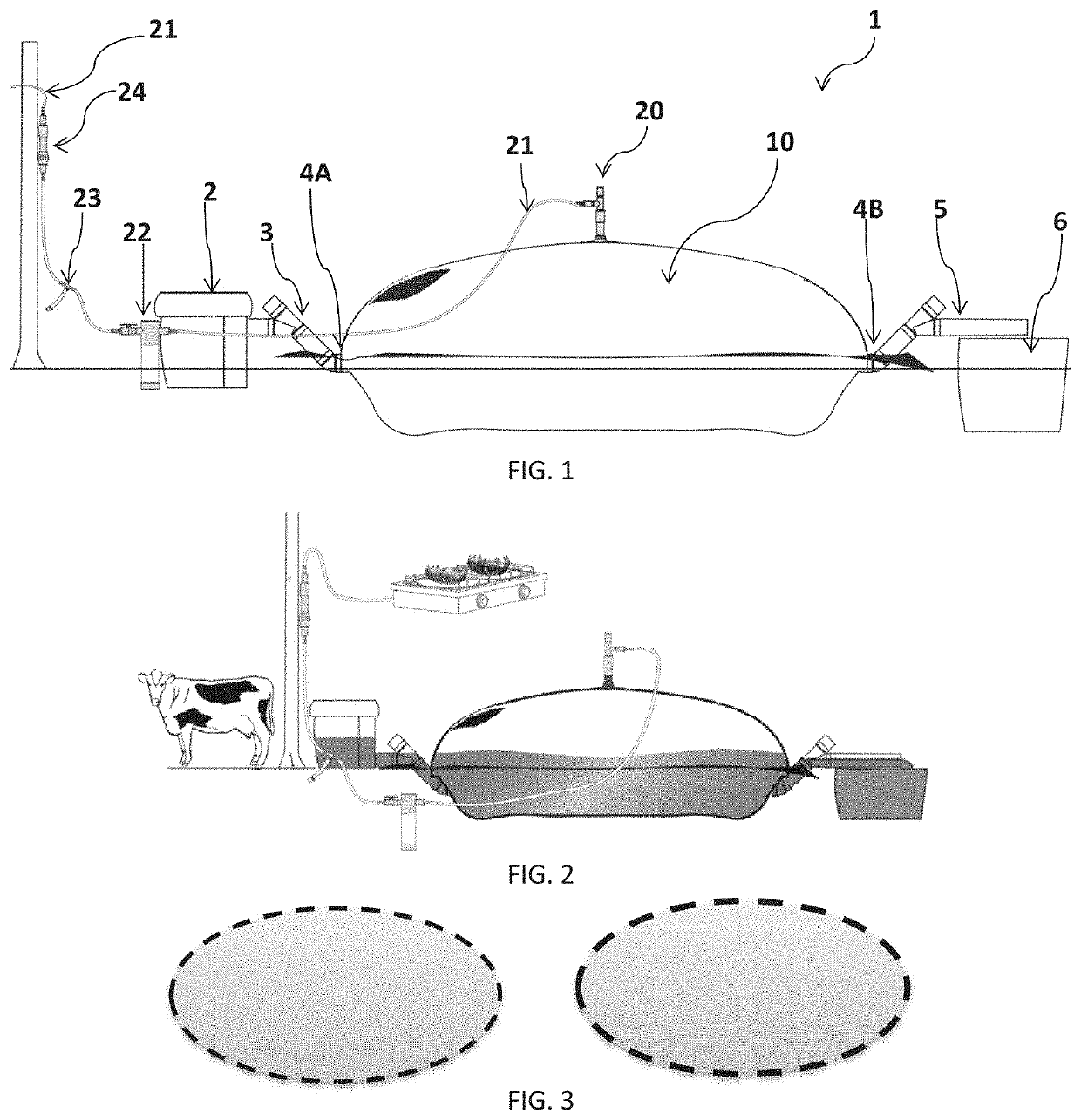
[0041]FIG. 1 shows an embodiment of the biodigester system 1 of the present invention, wherein said system 1 includes a reactor 10, a biogas outlet 20, a gas piping 21, an inlet flange 4A, an inlet piping 3, an inlet 2, an outlet flange 4B, an outlet piping 5, an outlet 6, a pr...


PUM

PropertyMeasurementUnit
temperatureaaaaaaaaaa
ignition temperatureaaaaaaaaaa
thicknessaaaaaaaaaa

Abstract

Methods, systems and / or apparatus related to the manufacture and use of biodigesters are disclosed. Moreover, techniques for the manufacture of reactors whose final shape increases the lifespan of said biodigester, as well as modular techniques for the manufacture of said reactors, are included.

Description

FIELD OF THE INVENTION[0001]The present invention relates generally to the field of biodigester systems, and more specifically, to a biodigester system including a reactor whose method of manufacture provides a longer lifespan than the average found in the art. The biodigester system includes, among others, an inlet, a reactor, and an outlet, wherein said biodigester system produces fertilizer and gas conditioned for domestic use. The biodigester system includes methods of manufacturing and using the same.BACKGROUND OF THE INVENTION[0002]Biodigester systems are widely known in the art. Thousands of years ago, man found that it is possible to obtain methane gas, also called as biogas, and a potent organic fertilizer, also called as biol, from organic matter (cattle feces, human feces, blended fruits and vegetables, etc.) through its fermentation with anaerobic bacteria. In its simplest form, a biodigester system is a hermetically or tightly sealed container (also called anaerobic rea...

Claims


Application Information

Patent Timeline
Patent Type & Authority Applications(United States)
IPC IPC(8): A01C3/02C12M1/12C12M1/107
CPCC12M21/04C12M23/06A01C3/023B65D88/16C12M23/14Y02E50/30Y02W30/40
Inventor EATON, ALEXANDER BENNET
Owner BUEN MANEJO DEL CAMPO S A DE
Why Eureka
Try Eureka