System for detecting an abnormality in a carbon dioxide separation membrane plant
- Summary
- Abstract
- Description
- Claims
- Application Information
AI Technical Summary
Benefits of technology
Problems solved by technology
Method used
Image
Examples
examples 1 to 5
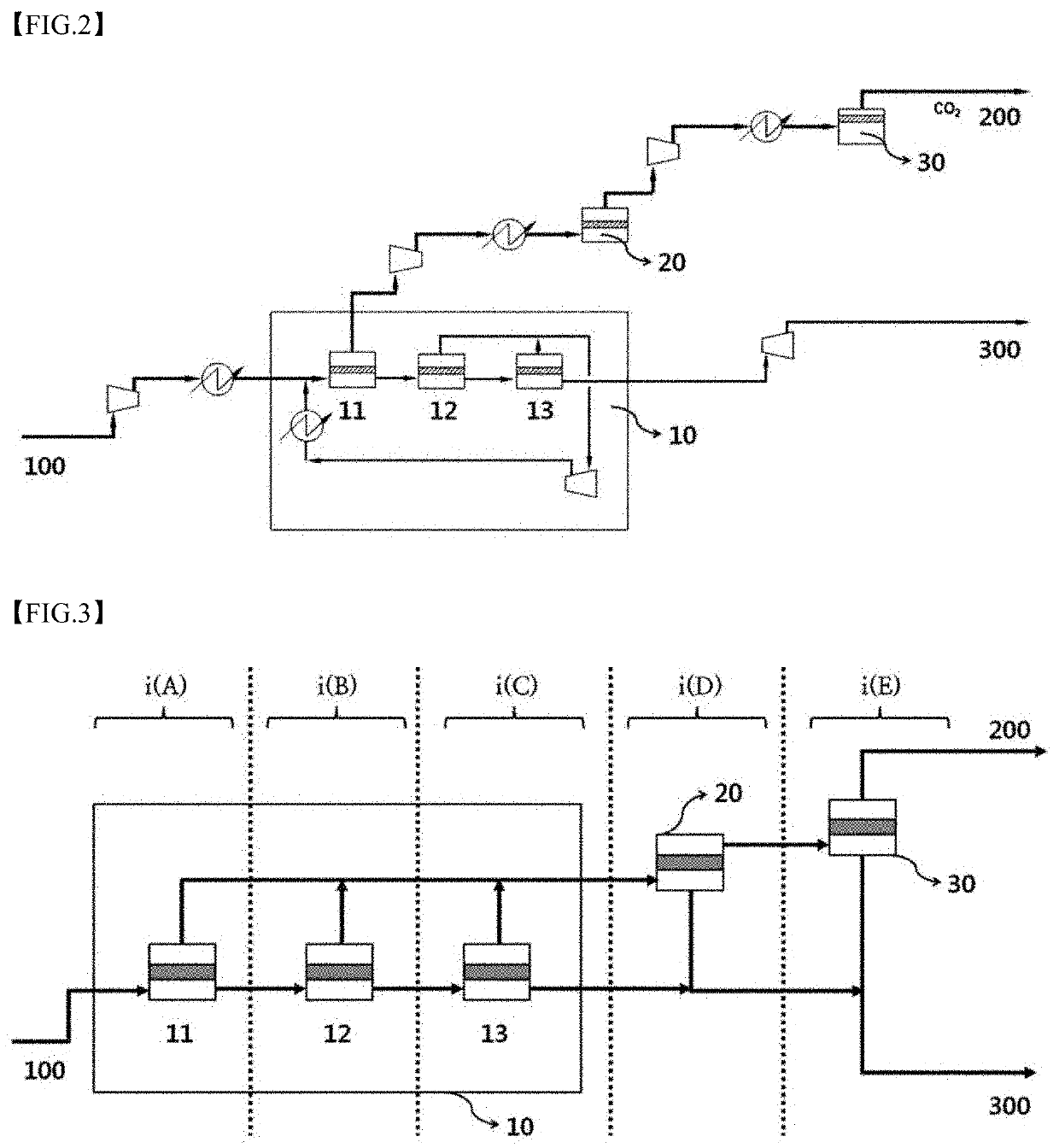
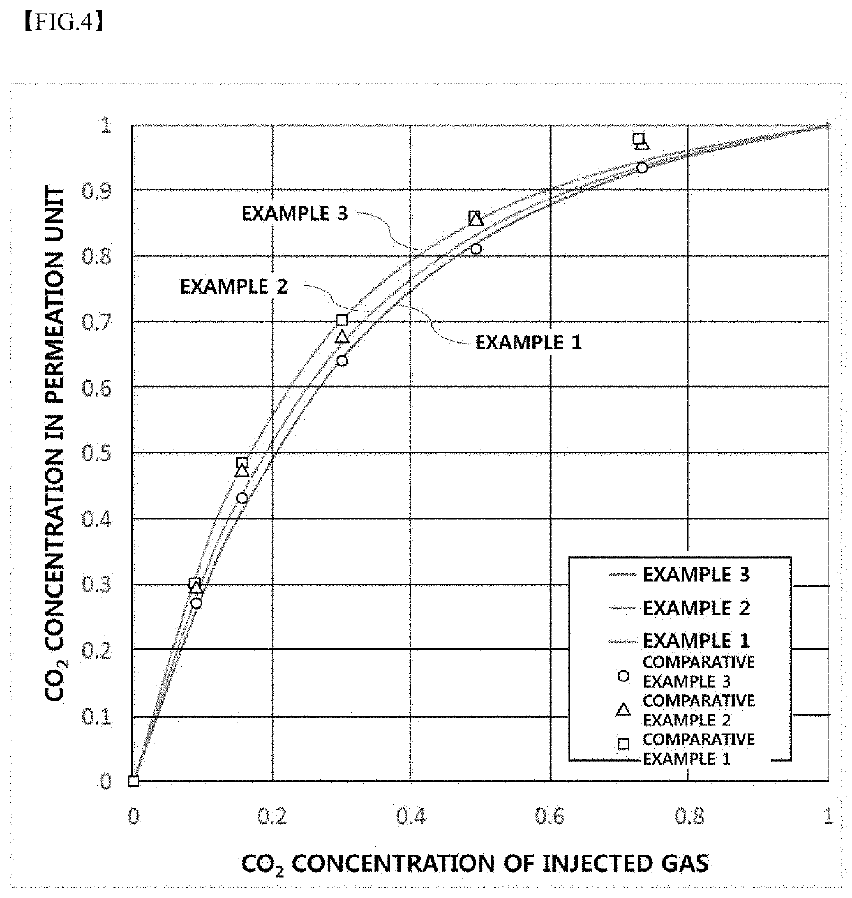
[0089]After configuring a CO2 separation membrane plant as illustrated in FIG. 2, measured variables were fitted using the above-described Equations 5 to 13 of the present invention through the MATLAB program, and 1.74 and 2.37 were obtained as m and n of Equation 13, respectively. Also, while changing flow rates and pressures in the plant as shown in Table 1 below, changes in CO2 concentration in the permeation unit due to the changes in the flow rates and pressures were predicted and shown using graphs in FIGS. 4 to 7.
TABLE 1VariableFlow rate (NL / min)Pressure (bar)Example 1701Example 2701.5Example 3702Example 4502Example 5882
PUM
 Abstract
Description
Claims
Application Information
 - R&D
- Intellectual Property
- Life Sciences
- Materials
- Tech Scout
- Unparalleled Data Quality
- Higher Quality Content
- 60% Fewer Hallucinations
Browse by: Latest US Patents, China's latest patents, Technical Efficacy Thesaurus, Application Domain, Technology Topic, Popular Technical Reports.
© 2025 PatSnap. All rights reserved.Legal|Privacy policy|Modern Slavery Act Transparency Statement|Sitemap|About US| Contact US: help@patsnap.com


