
Combination oil ring

Active Publication Date: 2019-11-28
TEIKOKU PISTON RING CO LTD
View PDF0 Cites 2 Cited by
  • Summary
  • Abstract
  • Description
  • Claims
  • Application Information

AI Technical Summary

Benefits of technology

The present invention provides a combination oil ring that can reduce oil consumption and friction during high-speed engine rotation with low oil ring tension. This results in improved performance and efficiency.

Problems solved by technology

However, the use of means for reducing the oil consumption may induce increase in friction.

Method used


Image

  • Combination oil ring
  • Combination oil ring
  • Combination oil ring

Examples


example 4

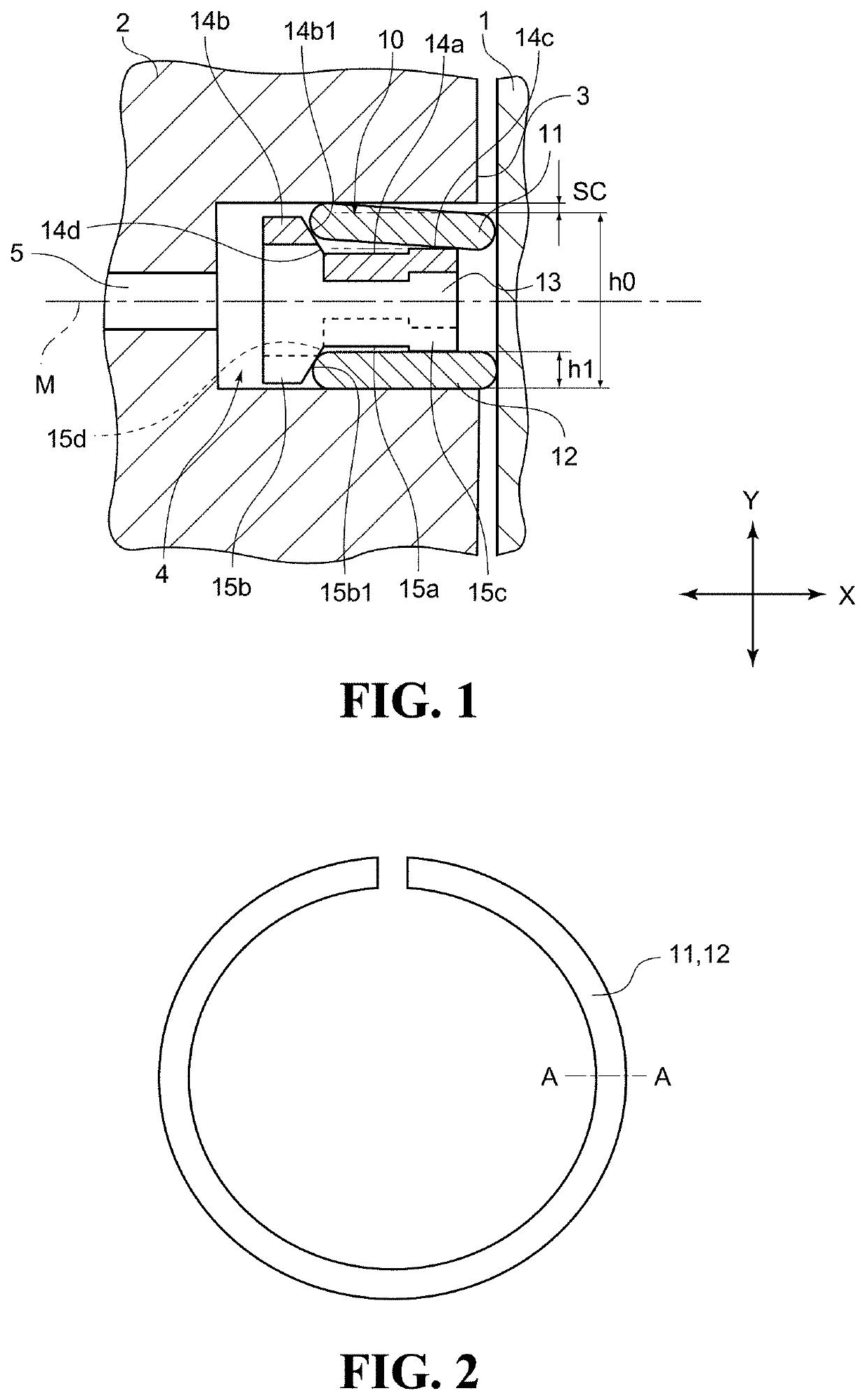
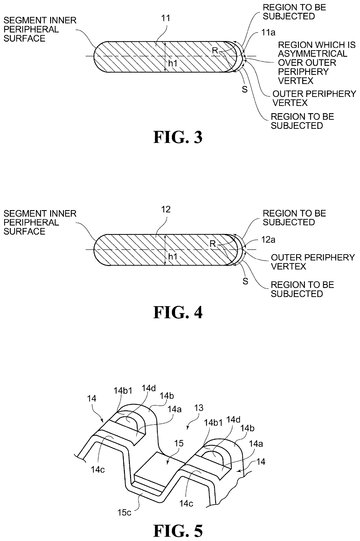
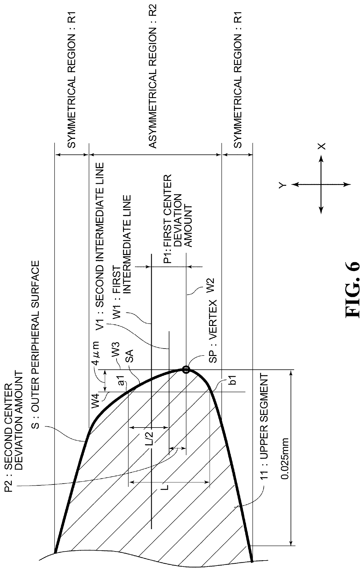
[0149 is a combination of the US4 being the upper segment 11 in which the segment outer peripheral shape of the distal end portion is set to the asymmetrical shape and the LS4 being the lower segment 12 in which the segment outer peripheral shape of the distal end portion is set to the symmetrical shape. Reference Example 5 is a combination of the LS4 being the upper segment 11 in which the segment outer peripheral shape of the distal end portion is set to the symmetrical shape and the LS4 being the lower segment 12 in which the segment outer peripheral shape of the distal end portion is set to the symmetrical shape. From the comparison above, it is preferred for reduction of oil consumption that the upper segment 11 in which the segment outer periphery distal end portion has the asymmetrical shape be employed. In Example 4, as compared to Reference Example 5, there can be seen reduction of 13% when the average piston velocity V=20.2 m / s is given.

[0150]Reference Example 4 is a combi...


PUM


Abstract

Provided is an oil ring. A shape of an outer peripheral surface of an upper segment arranged on an engine combustion chamber side has a symmetrical curved shape. A shape of an outer peripheral surface of a lower segment arranged on a side away from the engine combustion chamber is a symmetrical curved shape.

Description

TECHNICAL FIELD[0001]The present invention relates to a combination oil ring, which is to be attached to an oil ring groove of a piston.BACKGROUND ART[0002]A piston ring is attached to a piston ring groove formed in an outer periphery of a piston of an internal combustion engine. A piston ring for use in a typical gasoline internal combustion engine has a configuration including two compression rings (top ring and second ring) and a combination oil ring. The combination oil ring has an oil-control function, and is configured to suppress consumption of engine oil.[0003]In general, for the purpose of reducing an oil consumption, in a combination oil ring including two segments (side rails) and an expander spacer (spacer expander), there has been employed a general method of increasing an oil ring tension, or a method of increasing a drop (distance μm in a radial direction), without increasing the oil ring tension, from a vertex SP of an outer peripheral surface S (hereinafter referred...

Claims


Application Information

Patent Timeline
IPC IPC(8): F16J9/20F16J9/06F16J9/26
CPCF16J9/068F16J9/20F16J9/26
Inventor KAWANO, KENTAROTAMAKI, SEIJI
Owner TEIKOKU PISTON RING CO LTD
Learn More