
Grade crossing gate arm position detection system

Active Publication Date: 2019-11-21
C D L ELECTRIC CO INC
View PDF0 Cites 2 Cited by
  • Summary
  • Abstract
  • Description
  • Claims
  • Application Information

AI Technical Summary

Benefits of technology

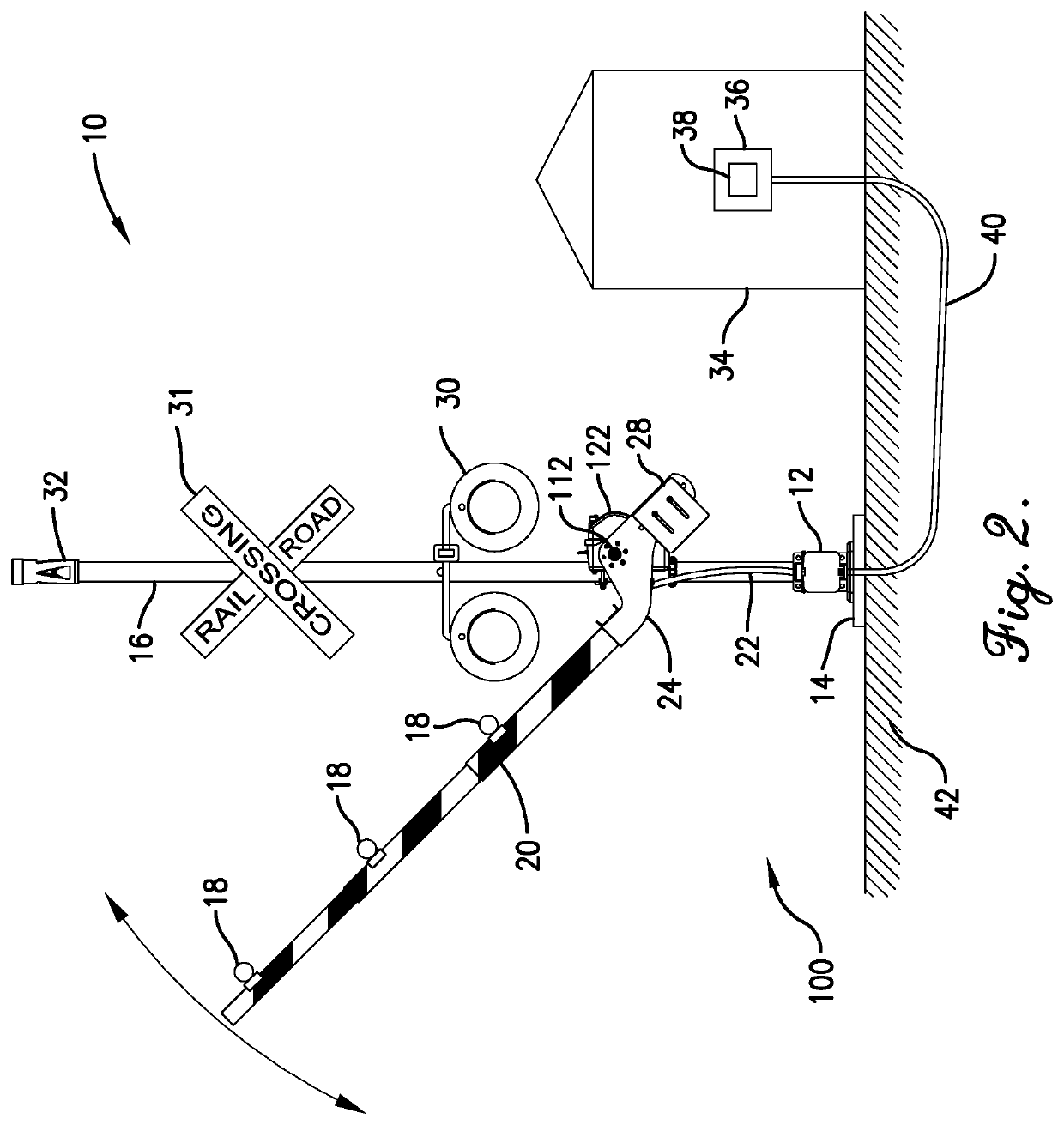
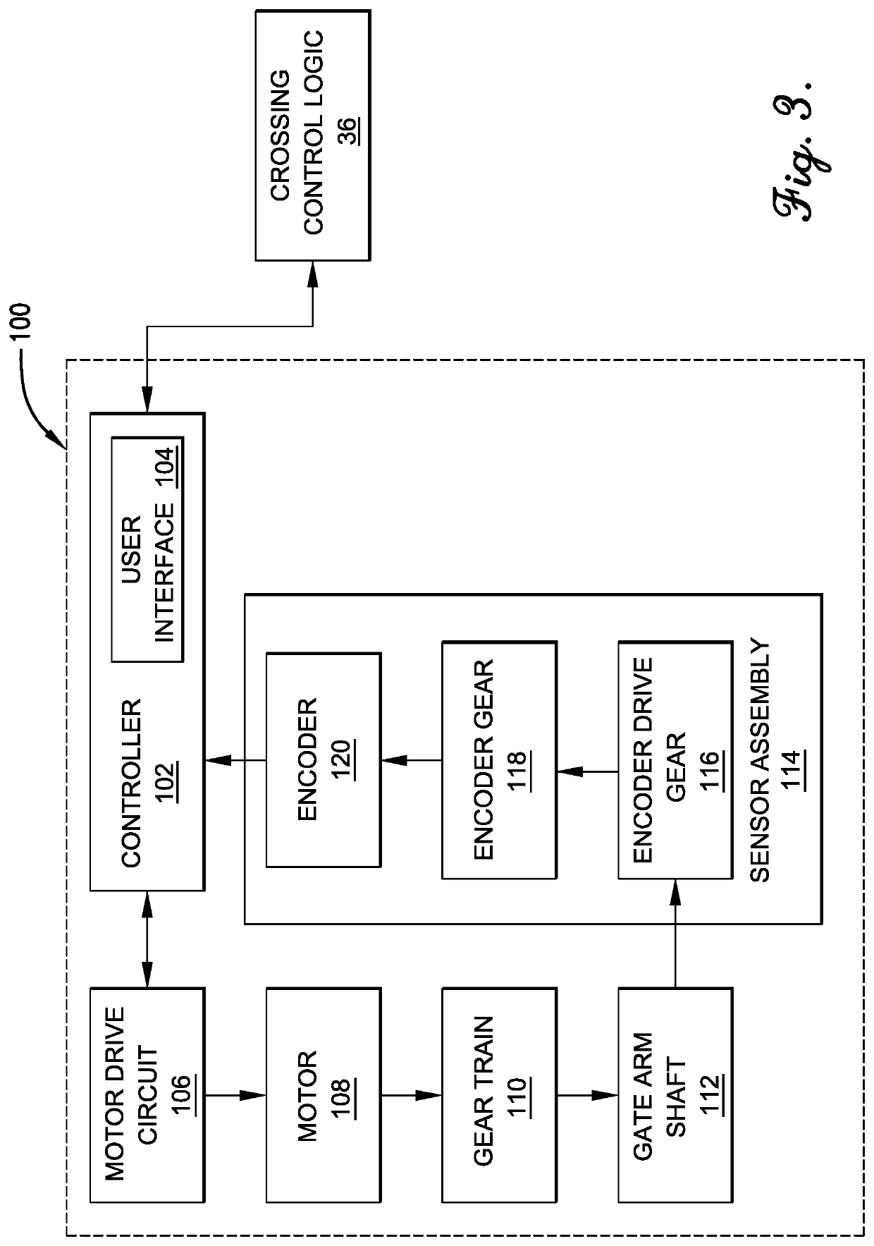
The patent describes a crossing gate mechanism that includes a swingable gate arm and a rotatable gate arm shaft fixed to the gate arm. The mechanism also includes an electronic sensor assembly that senses the position of the gate arm shaft and transmits a signal based on the position. The mechanism is designed to generate the position signal based on the rotation of the gate arm shaft. The technical effect of this invention is to provide a reliable and accurate mechanism for controlling the movement of a crossing gate.

Problems solved by technology

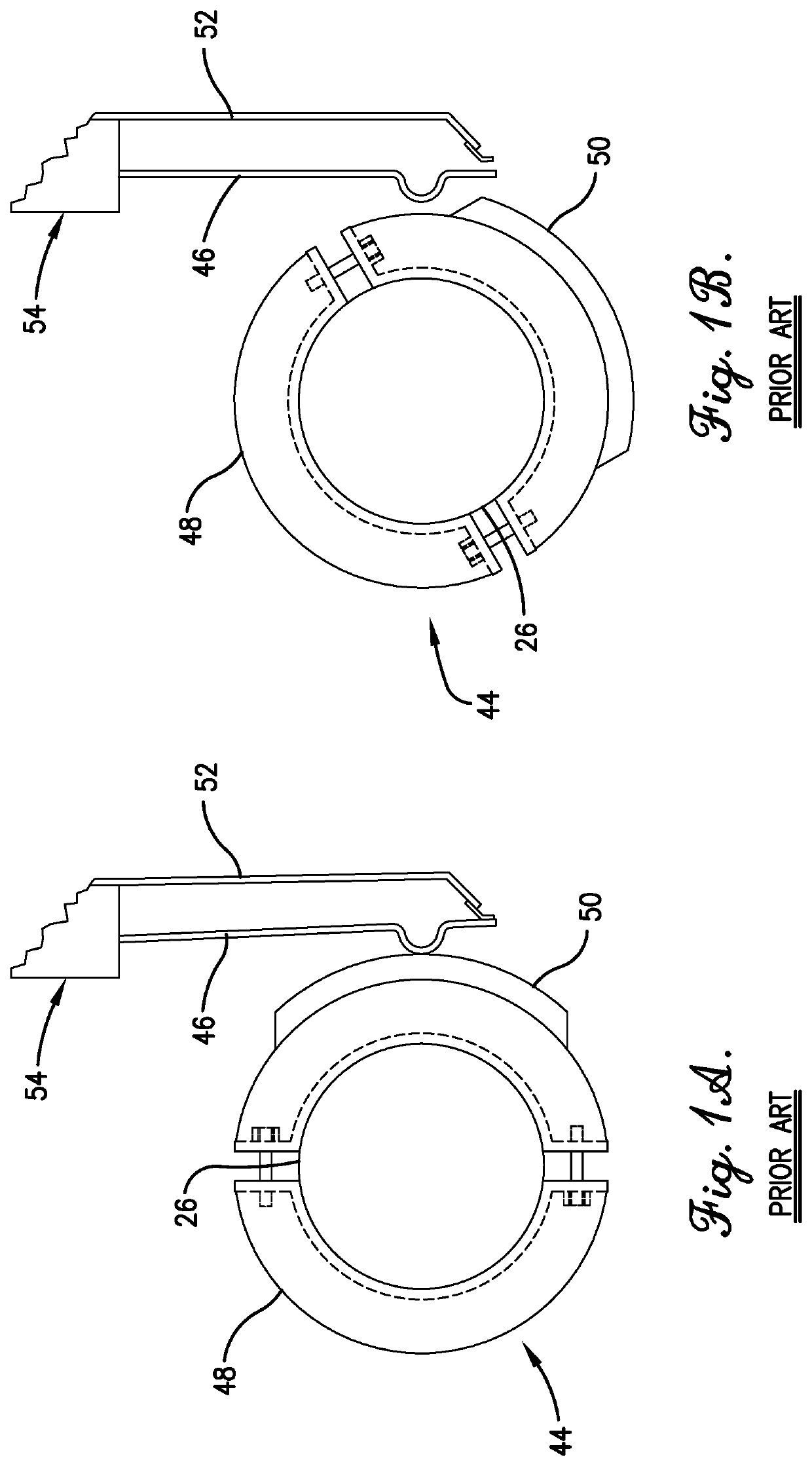
With this technique, there is no exact measurement of the angle at which the cam lobe is rotated.
However, having all the connections on the front side of the terminal board can make it difficult to diagnose or troubleshoot errors with the grade crossing gates system.
Moreover, the large number of wire connections can cause difficulty in ensuring that the proper connections are made prior to testing the grade crossing gates system.
With the cam lobe assembly 44, adjusting the rotational position of the lobe 50 can be very difficult.
In addition, if the cam lobe assembly 44 is not adjusted properly, the crossing gate system may not operate properly, leading to a possibly dangerous situation.

Method used


Image

  • Grade crossing gate arm position detection system
  • Grade crossing gate arm position detection system
  • Grade crossing gate arm position detection system

Examples


Embodiment Construction

[0060]The following detailed description of embodiments of the disclosure references the accompanying figures. The embodiments are intended to describe aspects of the disclosure in sufficient detail to enable those with ordinary skill in the art to practice the disclosure. The embodiments of the disclosure are illustrated by way of example and not by way of limitation. Other embodiments may be utilized, and changes may be made without departing from the scope of the claims. The following description is, therefore, not limiting. The scope of the present disclosure is defined only by the appended claims, along with the full scope of equivalents to which such claims are entitled.

[0061]In this description, references to “one embodiment,”“an embodiment,” or “embodiments” mean that the feature or features referred to are included in at least one embodiment of the disclosure. Separate references to “one embodiment,”“an embodiment,” or “embodiments” in this description do not necessarily re...


PUM


Abstract

A crossing gate mechanism includes a swingable gate arm, a rotatable gate arm shaft fixed to the gate arm, and an electronic sensor assembly coupled to the gate arm shaft. Rotation of the gate arm shaft corresponds with swinging of the gate arm. The electronic sensor assembly senses an angular position of the gate arm shaft and transmits a position signal corresponding thereto. The electronic sensor assembly includes a driving element that is attached to the gate arm shaft to rotate therewith. the electronic sensor assembly also includes a driven element that is driven by the driving element such that rotation of the gate arm shaft causes the driven element to rotate. The electronic sensor assembly is configured to generate the position signal based on a position of the gate arm shaft.

Description

CROSS-REFERENCE TO RELATED APPLICATIONSPriority Application[0001]The present application claims priority from U.S. Provisional Patent Application No. 62 / 674,412, filed May 21, 2018, and entitled GRADE CROSSING GATE MECHANISM, the entire disclosure of which is hereby incorporated by reference herein.Contemporaneously Filed Applications[0002]The present application is filed contemporaneously with U.S. patent application Ser. No. ______, entitled DOUBLE-SIDED TERMINAL BOARD FOR GRADE CROSSING GATE CONTROLLER, filed May 21, 2019; and U.S. patent application Ser. No. ______, entitled USER INTERFACE FOR GRADE CROSSING GATE CONTROLLER, filed May 21, 2019. The entire disclosure of each of the aforementioned contemporaneously filed applications is hereby incorporated by reference herein.FIELD OF THE DISCLOSURE[0003]The field of the disclosure relates generally to grade crossing gate mechanisms and, more particularly, to wire management and sensor systems for grade crossing gate mechanisms.BA...

Claims


Application Information

Patent Timeline
IPC IPC(8): B61L29/30B61L29/28B61L29/02B61L29/04B61L29/22
CPCB61L29/288B61L29/22B61L29/026B61L29/04B61L29/30B61L5/06B61L29/08G01B21/22
Inventor IBARRA, MARCO ANTONIOSAGE, DEVIN STEVENLAWSON, MICHAEL CARMEN
Owner C D L ELECTRIC CO INC
Learn More