Method and system for high resolution range and speedometers

a applied in the field of high-resolution range and speedometer technology, to achieve the effect of high accuracy, low bandwidth, and reliable, simple and fast manner

Active Publication Date: 2019-11-07
LAMBDA 4 ENTWICKLUNGEN
View PDF0 Cites 0 Cited by
  • Summary
  • Abstract
  • Description
  • Claims
  • Application Information

AI Technical Summary

Benefits of technology

The present invention aims to develop systems and methods for reliable, simple, and quick distance measurements with high accuracy in complicated environments and in the case of moving objects. The invention minimizes the effects of inaccuracy in frequency measurements and phase jumps by processing the object of measurement to eliminate or reduce the effects of phase jumps, multipath environments, and measurement errors. The processing includes halving the phase information or phase relationships and performing additional steps to reduce the difference between the phase information and the execution of the steps. The invention achieves a robust and accurate design.

Problems solved by technology

Since the first notional timepoint and the second notional timepoint usually differ at least slightly from one another in practice, a phase error—particularly in the magnitude of the time deviation between first notional timepoint and second notional timepoint multiplied by the frequency difference—generally arises in the event of frequency differences during the calculation of the theoretical phase relationship(s) for the notional timepoint(s).

Method used


Image

  • Method and system for high resolution range and speedometers

Examples


Embodiment Construction

[0104]Additional advantageous embodiments are to be described purely for the sake of example with reference to the schematic FIGURE that follows.

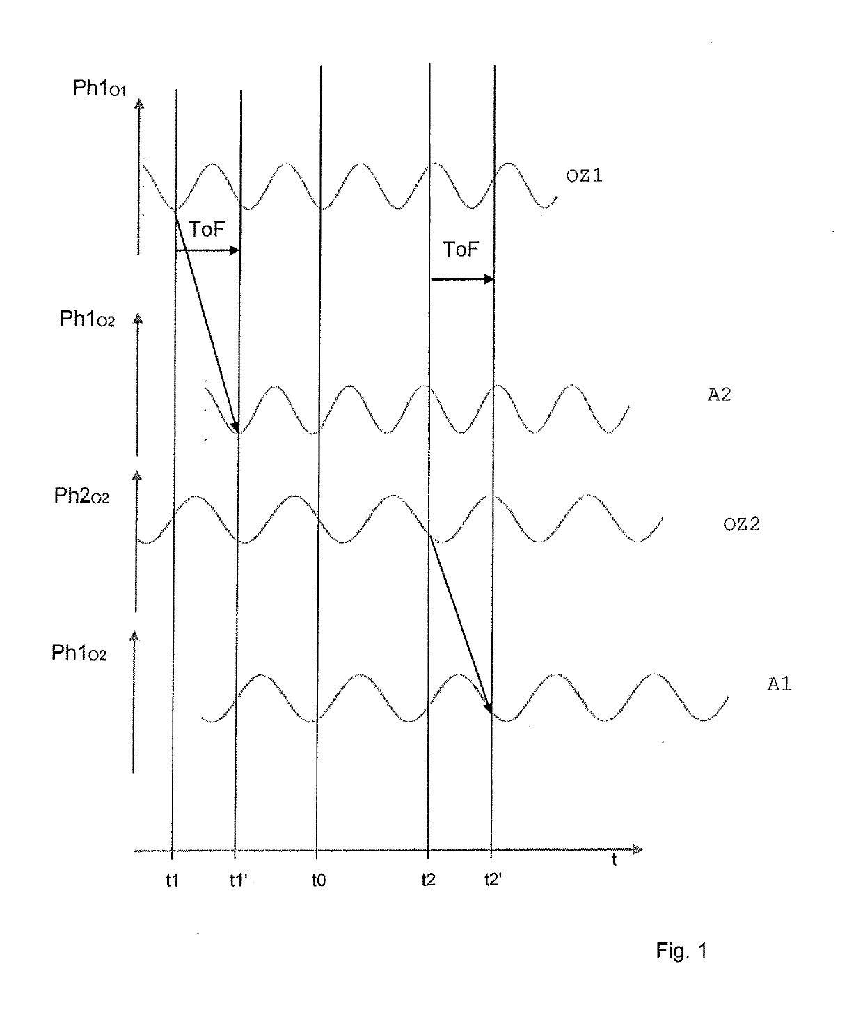
[0105]FIG. 1 shows an illustration of the phase relationships and times during an execution of steps a to d with two stationary objects O1 and O2. Shown on a common time axis are the phase relationship Ph1O1 of the oscillation of a first oscillator OZ1 at the first object O1 and the phase relationship Ph1O2 of the signal of the first oscillator OZ1 received by a second antenna A2 at the second object O2 and the phase relationship Ph2O2 of the oscillations of a second oscillator OZ2 at the second object O2 and the phase relationship Ph2O1 of the signal of the second oscillator OZ2 received by a first antenna A1 at the first object O1.

[0106]The transmission is denoted by an oblique arrow; the time of flight ToF of the signals is always denoted by a vertical arrow. t0, t1, t2, t2′ represent timepoints. At timepoint t0, the oscillators have a p...


PUM


Abstract

A method and a system for high-resolution measurement of distance between two objects by means of electromagnetic waves is such that measurements are performed in a reliable, simple, and quick manner with low bandwidth and high accuracy even in complicated multipath environments and / or with moving objects. The method includes determination of a supposed distance and / or supposed relative speed between first and second objects from an object of measurement by comparing the object of measurement with a set of stored and / or calculated reference objects of measurement. The reference objects of measurement relate to different distances and different relative speeds, each reference object being associated with a distance and a speed. The supposed distance and / or speed is assumed to be the distance and / or speed that is associated with the stored and / or calculated reference object of measurement that best fits, is closest to, and / or is most similar to the object of measurement.

Description

TECHNICAL FIELD[0001]The present invention relates to a method and a system for the high-resolution measurement of distance and / or speed by means of electromagnetic waves.BACKGROUNDBackground Information[0002]Systems and methods for measuring distance are abundantly known, for example from EP 2196823.SUMMARY[0003]It is the object of the present invention to further develop such systems and methods such that distance measurements can be performed in a reliable, simple, and quick manner with low bandwidth and high accuracy even in complicated multipath environments and / or in the case of moving objects.[0004]It is also an object to determine relative speeds, particularly low relative speeds, with limited of the signal transmission and / or analysis bandwidth with high accuracy, ideally together with the distance.[0005]This object is achieved by a method for the high-resolution determination of a distance and / or a speed between a first object (O1) and a second object (O2) by means of elec...

Claims


Application Information

Patent Timeline
IPC IPC(8): G01S13/76
CPCG01S13/762G01D21/02G01S11/02G01S13/84
Inventor REIMANN, RÖNNE
Owner LAMBDA 4 ENTWICKLUNGEN
Why Eureka
Try Eureka