
Tube with indication function

a technology of indication function and tube, which is applied in the direction of reflex reflectors, instruments, other domestic objects, etc., can solve the problems of poor ability to find out or recognize small tubes of cable conduits or oxygen supply conduits, poor environmental light and human vision, and people who are nervous, etc., to achieve the effect of being readily identified

Inactive Publication Date: 2019-11-07
TOFORD PLASTIC MFG CORP
View PDF3 Cites 1 Cited by
  • Summary
  • Abstract
  • Description
  • Claims
  • Application Information

AI Technical Summary

Benefits of technology

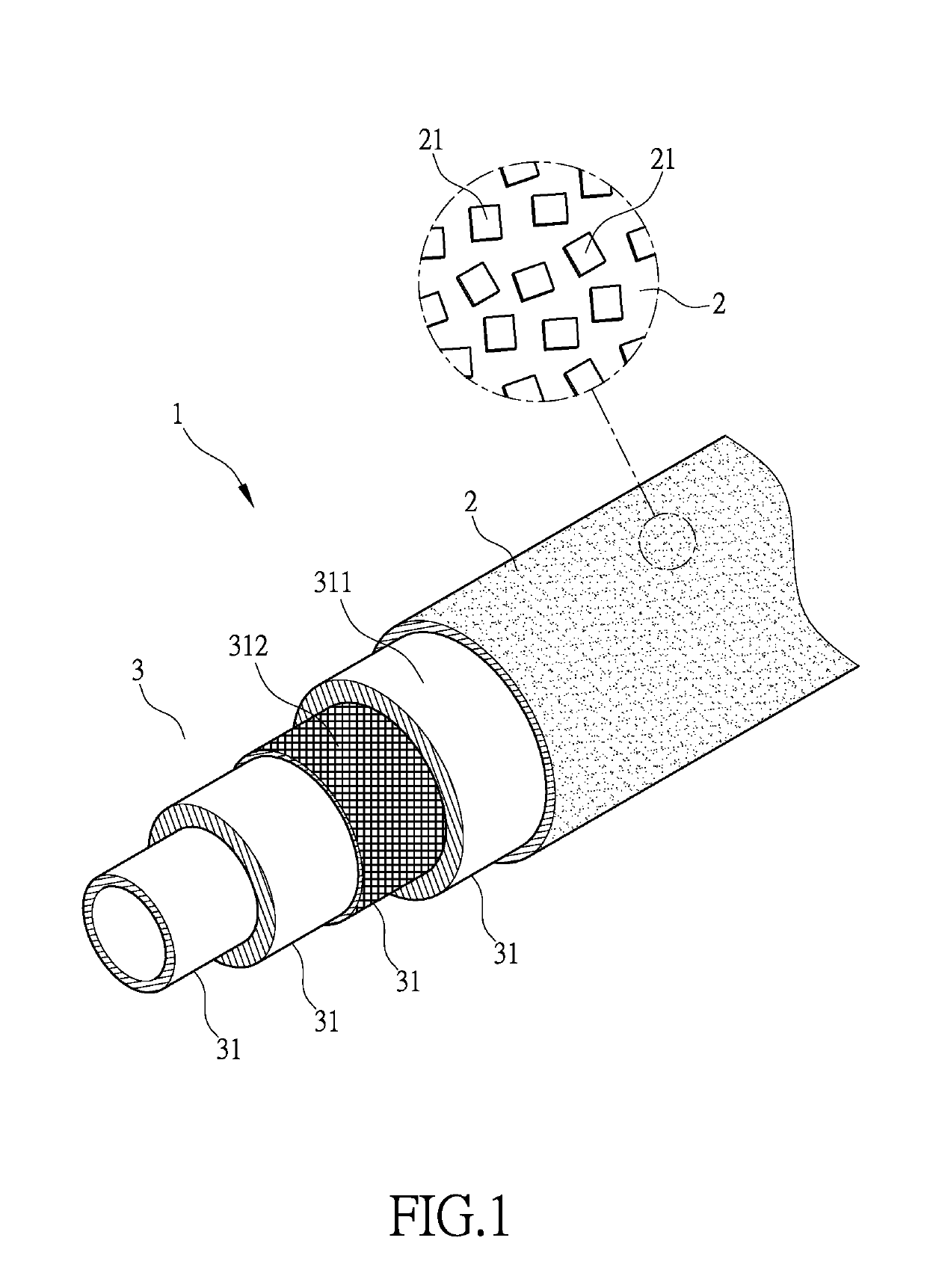
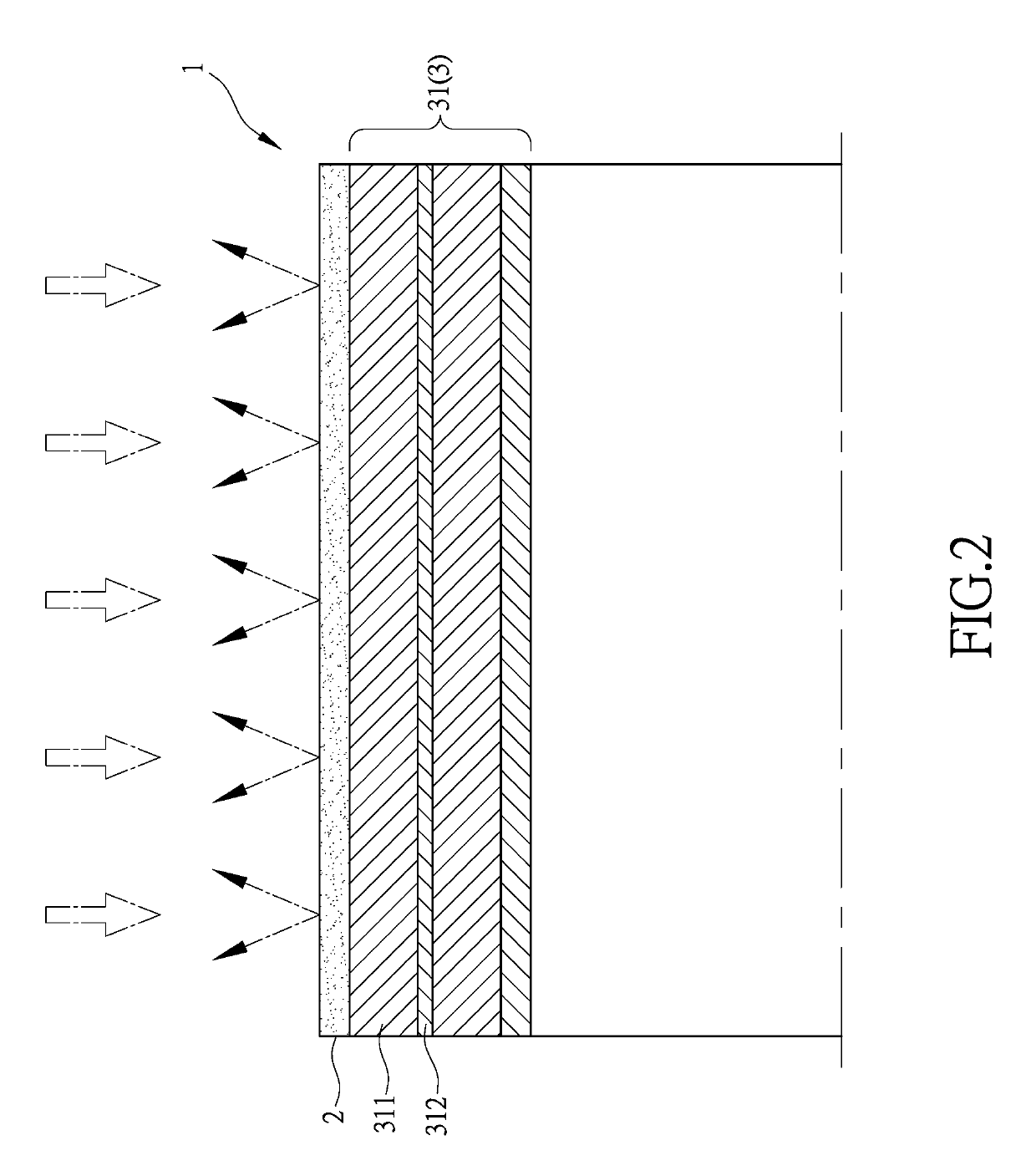
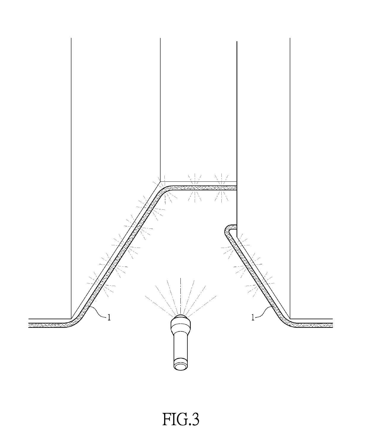
The present invention is a tube that has a reflection layer that reflects light incident on it. When the tube is located in a dark environment and exposed to light, the light is reflected by the reflectors embedded in the reflection layer and transmitted out through the tube. This makes the tube easily noticeable and easily identifiable.

Problems solved by technology

However, in such a dark environment, even a torch or a head light is used for lighting, such lighting is generally poor or insufficient, making the environment dim and human vision would be poor.
In case of emergency, due to being set in tension, people who are nervous would exhibit poor capability in finding out or recognizing small tubes of cable conduits or oxygen supply conduits in such a dim or dark environment.
This means the potential risk for such people is escalating with the lapse of time spent in looking for such conduits.
This is threatening to people staying in such an environment and facing such a trouble.
However, this would require additional expense for attaching the stickers to the tubes.
In addition, the stickers, which are exposed outside the tubes or conduits, may get detached from the tube due to deterioration of adhesive of the stickers after a long lapse of time or due to being removed inadvertently.
In addition, residues of the adhesive of the stickers may be left on the outside surfaces of the tubes once the stickers are removed.
Additional costs are necessary for handling such residue of adhesive.
These are just some factors that cause inconvenience of using the light-reflecting stickers for such a purpose.

Method used


Image

  • Tube with indication function
  • Tube with indication function
  • Tube with indication function

Examples


Embodiment Construction

[0013]The following descriptions are exemplary embodiments only, and are not intended to limit the scope, applicability or configuration of the invention in any way. Rather, the following description provides a convenient illustration for implementing exemplary embodiments of the invention. Various changes to the described embodiments may be made in the function and arrangement of the elements described without departing from the scope of the invention as set forth in the appended claims.

[0014]Firstly, referring to FIG. 1, the present invention provides a tube with indication function. The tube 1 of the present invention comprises, at least, a reflection layer 2 and an organization layer 3. The reflection layer 2 is located on the outermost layer of the tube 1. The reflection layer 2 is transparent and comprises reflectors 21, which are reflective to light, distributed densely in an interior thereof. The organization layer 3 is connected to and located under the reflection layer 2 a...


PUM

PropertyMeasurementUnit
transparentaaaaaaaaaa
coloraaaaaaaaaa
reflectionaaaaaaaaaa

Abstract

A tube with indication function is provided, including a reflection layer and an organization layer. The reflection layer is located on the outermost layer of the tube. The reflection layer is transparent and includes a number of reflectors that are capable of reflecting light densely distributed therein. With the tube being set up in a dark environment and irradiated with light, the light may transmit through the transparent reflection layer to reach the reflectors distributed in the reflection layer such that the reflectors reflect the light back to project the light outward. The reflection of light makes the tube noticeable to achieve an effect of indication, allowing a user to visually identify the location of the tube.

Description

(a) TECHNICAL FIELD OF THE INVENTION[0001]The present invention relates generally to a tube with indication function, and more particularly to a tube with indication function that can quickly show up through reflection of light upon being irradiated with light in a dark environment so as to allow people to easily identify where the tube is currently located.(b) DESCRIPTION OF THE PRIOR ART[0002]Conveyance of liquid or gas is often made with tubes and pipes. Tubes that are used for such a purpose of conveyance are generally of two types, one being rigid tubes, the other being flexible ones. Rigid tubes are often used in permanent and fixed construction jobs, while flexible tubes are used for temporary operations and jobs.[0003]The flexible tubes are generally resilient and curvable, making it possible to fit to different terrain configurations. Due to such characteristics, the flexible tubes are often involved in applications in special environments, such as electric cable conduits a...

Claims


Application Information

Patent Timeline
Patent Type & Authority Applications(United States)
IPC IPC(8): F16L11/12G02B17/00B32B27/12B32B1/08B32B27/20
CPCB32B2307/412B32B2597/00B32B27/20H02G3/0481B32B27/12B32B2307/402B32B1/08F16L11/124G02B17/002B32B2307/416B32B5/02B32B2250/05G02B5/12G02B5/13H02G2200/20
Inventor CHENG, FU-CHIA
Owner TOFORD PLASTIC MFG CORP
Learn More