Multi-level cardiac implant

a cardiac implant and multi-level technology, applied in the field of cardiac valve prosthesis, can solve the problems of valve malfunction, chordae becoming stretched, leaflets falling off,

Active Publication Date: 2019-11-07
MITRASSIST MEDICAL
View PDF0 Cites 27 Cited by
  • Summary
  • Abstract
  • Description
  • Claims
  • Application Information

AI Technical Summary

Benefits of technology

The patent describes a heart valve prosthesis that includes a frame with supports and wires that are designed to create a natural heart valve leaflet look. The frame has a unique design that allows for flexibility and can be expanded and compressed for delivery through a catheter. The wires are arranged as arcs connecting the supports, and there are at least two rings of wires that circumnavigate the center lumen of the frame. The frame has a multi-pointed shape and includes a number of points which is a multiple of three. The prosthesis also includes flexible leaflets attached to the frame, which can open and close to fluid pressure in a downstream direction. The technical effects of this invention include a more natural heart valve leaflet look, improved flexibility, and better ability to repair and replace damaged heart valves.

Problems solved by technology

Valve malfunction can result from the chordae becoming stretched, and in some cases tearing.
When a chord tears, the result is a flailed leaflet.
Also, a normally structured valve may not function properly because of an enlargement of the valve annulus pulling the leaflets apart.
This condition is referred to as a dilation of the annulus and generally results from heart muscle failure.
In addition, the valve may be defective at birth or because of an acquired disease, usually infectious or inflammatory.

Method used


Image

  • Multi-level cardiac implant
  • Multi-level cardiac implant
  • Multi-level cardiac implant

Examples


Embodiment Construction

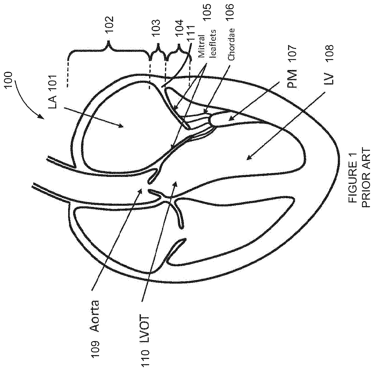
[0152]The present invention, in some embodiments thereof, relates to a cardiac valve prosthesis, and more particularly, but not exclusively, to a cardiac valve prosthesis for a mitral valve.

Introduction

[0153]The term “frame” is used throughout the present specification and claims to mean a support for a cardiac valve. In some embodiments, the cardiac valve is optionally a tissue or sheet of material or fabric designed to act as a cardiac valve, attached to the frame. In some embodiments the cardiac valve is optionally a plastic and / or synthetic and / or metal valve.

[0154]The term “heart valve prosthesis” is used throughout the present specification and claims to mean a for a cardiac valve prosthesis, which includes an artificial valve and one or more supporting and / or anchoring frame(s). Example embodiments of the present invention are described with reference to the mitral valve. However, examples provided with reference to the mitral valve are also applicable to the tricuspid valve,...


PUM

PropertyMeasurementUnit
diameteraaaaaaaaaa
diameteraaaaaaaaaa
pressure loadsaaaaaaaaaa

Abstract

A heart valve prosthesis including a frame, the frame including a plurality of struts designed to extend from an upstream side of a natural heart valve to a downstream side of the natural heart valve, and a plurality of connectors attached to the plurality of struts, wherein the plurality of connectors are arranged as arcs connecting the struts, the arcs having two ends, each end attached to one of the struts, and a peak pointing from a center of the frame circumferentially outward and toward the upstream side of the frame, and the plurality of connectors are arranged as at least two rows, each row circumnavigating the center lumen of the frame. Related apparatus and methods are also described.

Description

RELATED APPLICATION / S[0001]This application claims priority from U.S. Provisional Patent Application No. 62 / 444,835 filed 11 Jan. 2017, the contents of which are incorporated herein by reference in their entirety.FIELD AND BACKGROUND OF THE INVENTION[0002]The present invention, in some embodiments thereof, relates to a cardiac valve prosthesis, and more particularly, but not exclusively, to a cardiac valve prosthesis for a mitral valve.[0003]The mitral valve and tricuspid valve are unidirectional heart valves which separate the left and right atria respectively, from corresponding heart ventricles. These valves have a distinct anatomical and physiological structure, having two (mitral) or three (tricuspid) sail-like leaflets connected to a sub-valvular mechanism of strings (chordae tendinae) and papillary muscles forming a part of the heart's ventricular shape, function and size.[0004]The heart has four chambers: the right and left atria, and the right and left ventricles. The atria...

Claims


Application Information

Patent Timeline
Patent Type & Authority Applications(United States)
IPC IPC(8): A61F2/24
CPCA61F2/2418A61F2250/0039A61F2/2415A61F2/243A61F2/2466A61F2/2445A61F2/91A61F2230/0093A61F2002/825A61F2220/0075A61F2230/0065A61F2210/0014B29C48/13B29L2031/7534B29K2705/08B29C48/151
Inventor NAOR, GILMEYER-BRODNITZ, GIDEON
Owner MITRASSIST MEDICAL
Why Eureka
Try Eureka