Device for driving a compressor
- Summary
- Abstract
- Description
- Claims
- Application Information
AI Technical Summary
Benefits of technology
Problems solved by technology
Method used
Image


Examples
Embodiment Construction
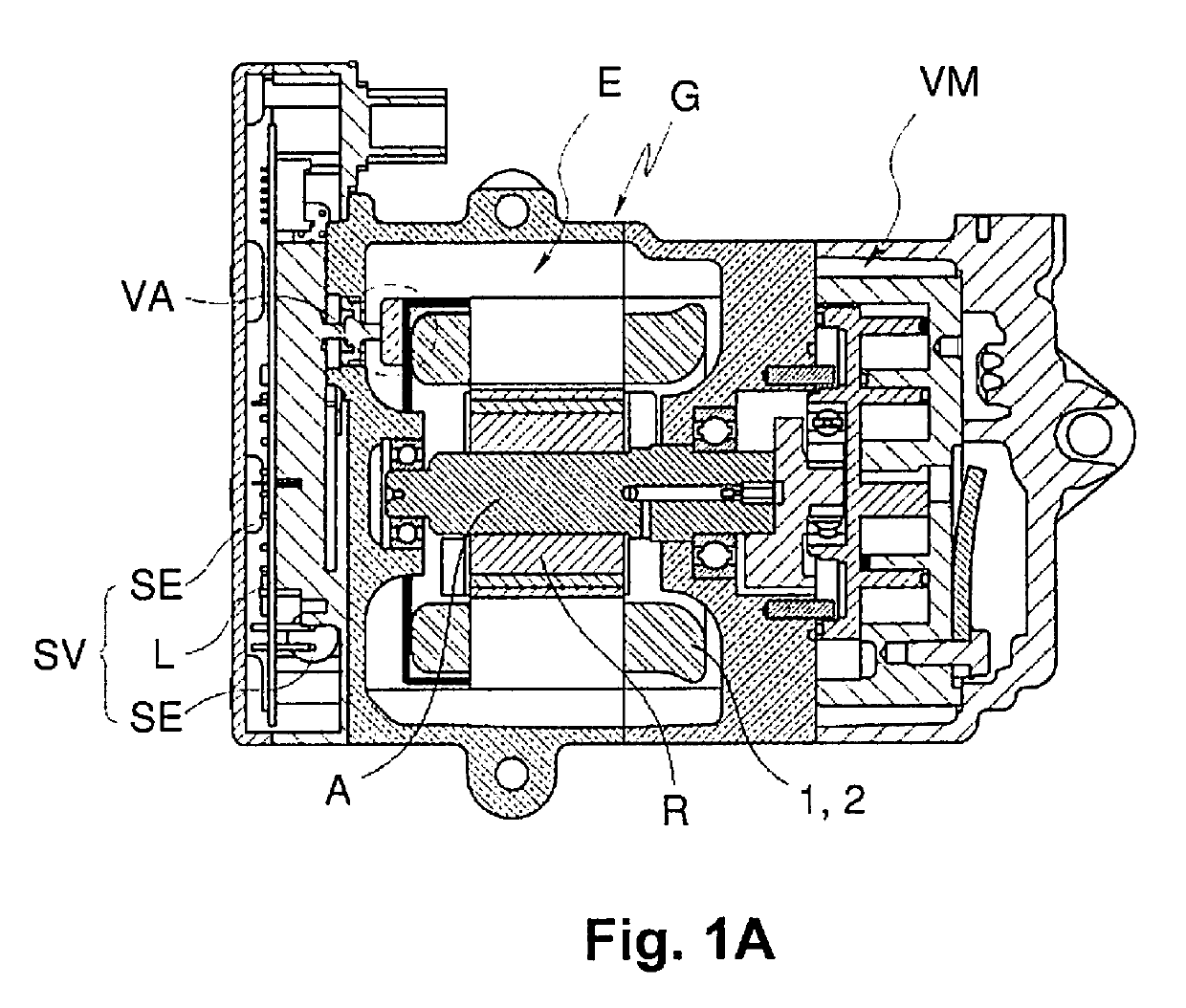
[0045]FIG. 1A shows in sectional representation an electrically driven compressor with an electric motor E disposed in a housing G as a device for driving a compressor mechanism VM. The electric motor E is supplied with energy across a switching means SV.
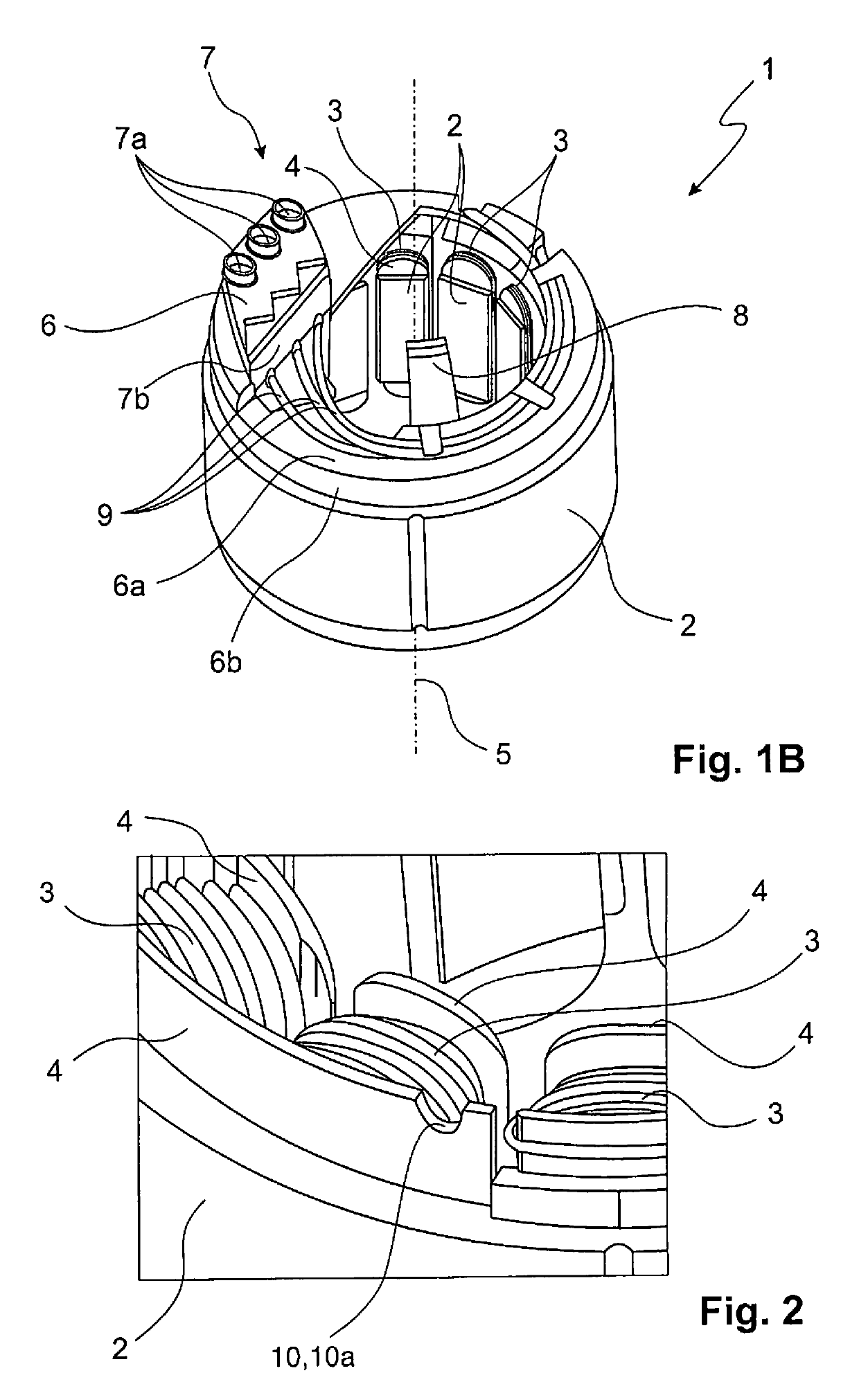
[0046]The electric motor E comprises a stator 1 with a substantially hollow cylindrical stator core 2 and coils wound onto the stator core 2 as well as a rotor R disposed within the stator 1. The rotor R is set into rotational motion when the coils of the stator 1 are supplied with electrical energy across a connection arrangement VA. The connection arrangement VA is developed on an end side of the stator 1 and comprises a multiplicity of electrical connections.
[0047]The rotor R is disposed coaxially within the stator 1 and rotatably about a rotational axis. A driving shaft A can be implemented integrally with the rotor R or as a separate element.
[0048]The electric motor E as well as the compression mechanism VM, developed as a scro...
PUM
 Abstract
Description
Claims
Application Information
 - R&D
- Intellectual Property
- Life Sciences
- Materials
- Tech Scout
- Unparalleled Data Quality
- Higher Quality Content
- 60% Fewer Hallucinations
Browse by: Latest US Patents, China's latest patents, Technical Efficacy Thesaurus, Application Domain, Technology Topic, Popular Technical Reports.
© 2025 PatSnap. All rights reserved.Legal|Privacy policy|Modern Slavery Act Transparency Statement|Sitemap|About US| Contact US: help@patsnap.com