
Wafer boat and method of manufacturing the same

a technology of wafer boat and wafer boat, which is applied in the direction of basic electric elements, electrical apparatus, and semiconductor devices, can solve the problem that the sic wafer has a high possibility of dropping from the wafer boat, and achieve the effect of reducing the drop of the sic wafer

Inactive Publication Date: 2019-10-24
MITSUBISHI ELECTRIC CORP
View PDF47 Cites 2 Cited by
  • Summary
  • Abstract
  • Description
  • Claims
  • Application Information

AI Technical Summary

Benefits of technology

The patent describes a special boat designed to prevent damage to silicon carbide wafers during transportation. The technical effect of this invention is to reduce the likelihood of defective wafers being produced due to damage during transportation.

Problems solved by technology

The patent text describes a heat treatment process for semiconductor wafers, specifically silicon carbide wafers, which are increasingly in demand for use in power semiconductor devices. The technical problem addressed in the patent is the high possibility of dropping the slippery SiC wafers from the wafer boat during transportation and heat treatment, which can result in damage to the wafers. The patent proposes a solution to this problem through the use of a heat treatment boat that reduces slipping caused by heat stress and self-weight stress.

Method used


Image

  • Wafer boat and method of manufacturing the same
  • Wafer boat and method of manufacturing the same
  • Wafer boat and method of manufacturing the same

Examples


embodiment

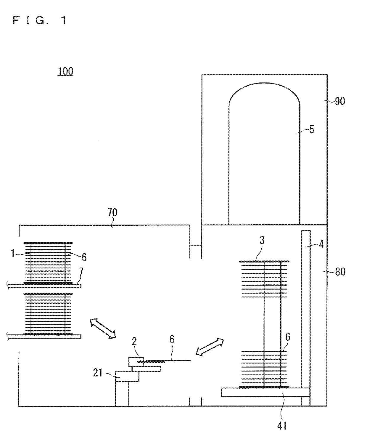
[0014]FIG. 1 is a schematic view illustrating a configuration of a vertical batch heat treatment apparatus 100 using a wafer boat of an embodiment according to the present invention. As illustrated in FIG. 1, the vertical batch heat treatment apparatus 100 includes a carrier chamber 70 for transferring a wafer carrier 1 capable of storing a plurality of SiC wafers 6 to and from an outside of the apparatus, a boat chamber 80 communicated with the carrier chamber 70 and store a quartz wafer boat 3 having the plurality of SiC wafer 6 so that their main surfaces vertically face each other, and a heat treatment chamber 90 provided on an upper side of the boat chamber 80 and having a heat-treating furnace 5 which performs a heat treatment on the plurality of SiC wafers 6 together with the wafer boat 3. The wafer boat 3 excel in heat resistance can be obtained by using quartz. Sapphire is also considered as a material of the wafer boat 3.

[0015]The wafer carrier 1 is provided on a carrier s...


PUM


Abstract

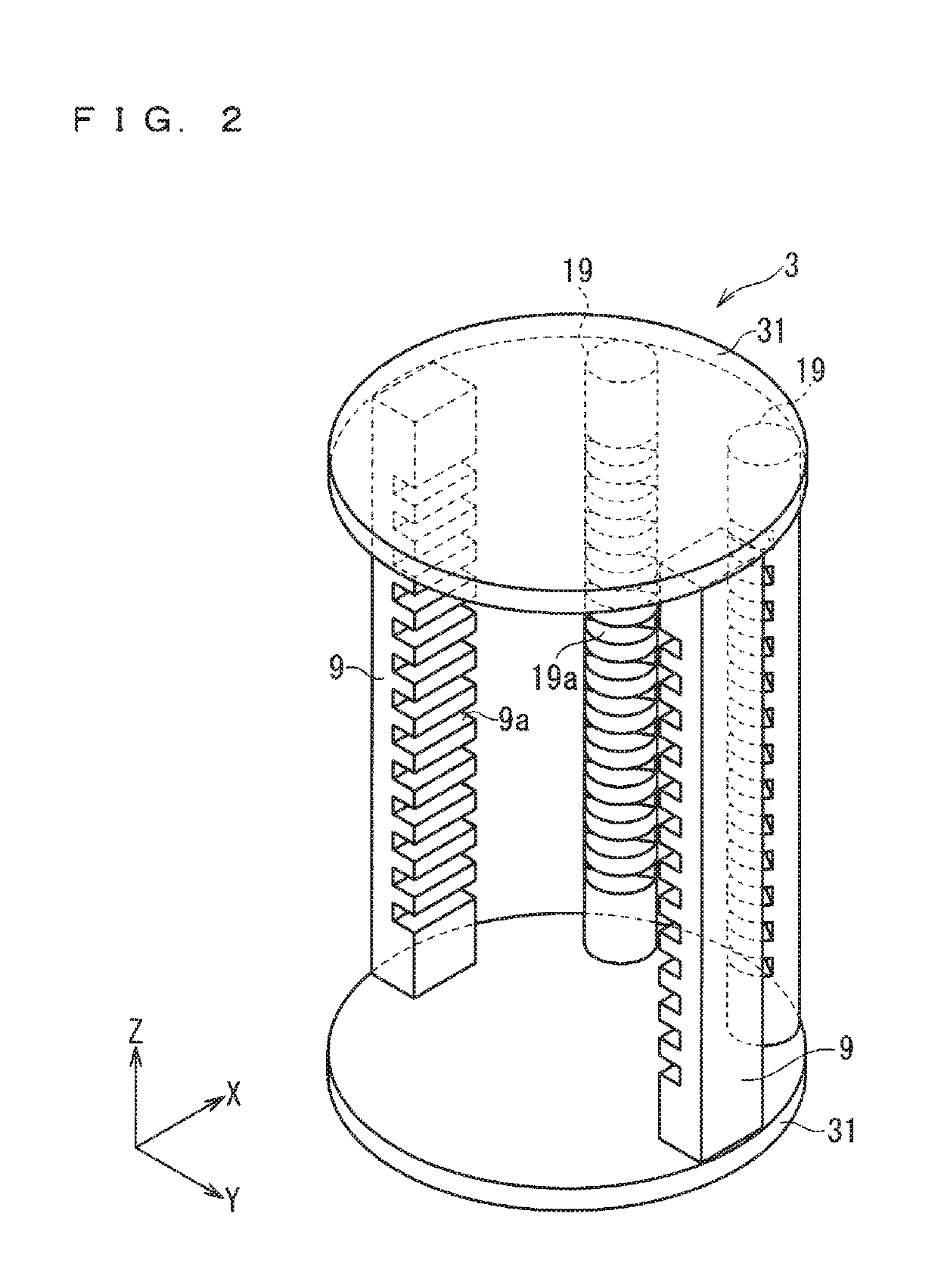
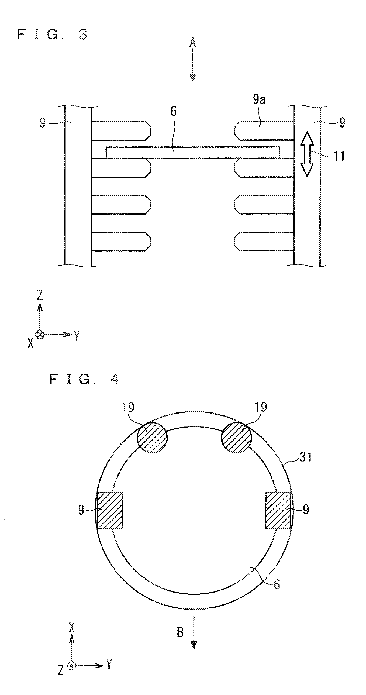
Provided is a wafer boat having a plurality of SiC wafers mounted on the water boat so that main surfaces of the plurality of the SiC wafers vertically face each other. The wafer boat includes a wafer support member in which a plurality of wafer shelves supporting the plurality of the SiC wafers are provided along an arrangement direction of the plurality of the SiC wafers, and a surface roughness of at least the wafer support member is equal to or larger than 2 μm and equal to or smaller than 4 μm at Ra value.

Description


Claims


Application Information

Patent Timeline
Owner MITSUBISHI ELECTRIC CORP
Learn More