Ultrasound device contacting

Active Publication Date: 2019-10-24
KONINKLJIJKE PHILIPS NV
View PDF0 Cites 2 Cited by
  • Summary
  • Abstract
  • Description
  • Claims
  • Application Information

AI Technical Summary

Benefits of technology

The device described in this patent has the ability to control the pressure and temperature during ultrasound imaging. It uses an elastomer layer with conductive particles to measure pressure and a further elastomer layer with temperature-sensitive conductivity to measure temperature. This allows for better control and prevention of overheating. The device also has the ability to adjust the actuation level to a desired level and can use a bias spring to aid in reducing pressure. Overall, the device improves the accuracy and safety of ultrasound imaging.

Problems solved by technology

Such applications face several challenges.
For instance, in imaging applications it is far from trivial to achieve a good contact between the ultrasound transducer array and the part of the body to be imaged.
A very low pressure or no contact results in poor acoustic coupling.
A high contact pressure leads to discomfort, safety issues or impact / mechanical damage.
However, a drawback of this approach is that usually large amounts of gel have to be used, which may contain air bubbles that interfere with the transmission or reception of the ultrasound signals.
Moreover, the ultrasound transducer array, e.g. in the form of the probe, is typically hand-held during an imaging procedure, which makes the procedure prone to errors.
In addition, there are instances where a hand-held solution is not viable, such as for example when imaging is performed from locations inside the body.
This for example applies to large area ultrasound transducers (e.g. wearable US patches) and transesophageal echocardiogram (TEE) probes, where it is notoriously difficult to establish a good contact between the ultrasound transducers and the body region to be imaged or treated.
Manual manipulation of ultrasound probes is also difficult when imaging is done as part of monitoring over a longer periods of time such as for example longer than hours, either continuously or with multiple imaging instances distributed during the monitoring time.
Similar challenges exist in therapeutic applications, where the focused beam requires periodic readjustment to treat multiple regions of the diseased tissue.
The manual adjustment is prone to inaccuracies and the range of phase controlled beam steering may not be sufficient to reach all diseased tissue without array displacement.

Method used


Image

  • Ultrasound device contacting
  • Ultrasound device contacting
  • Ultrasound device contacting

Examples


Embodiment Construction

[0044]In the context of the present application, the term ‘conductive’ means ‘electrically conductive’ unless explicitly stated otherwise. Similarly, the term ‘non-conductive’ means ‘electrically insulating’ unless explicitly stated otherwise. Instead of conductivity, resistivity can be measured. This is considered equivalent as both conductivity and resistivity are parameters for indicating the extent to which a material is capable of conducting current.

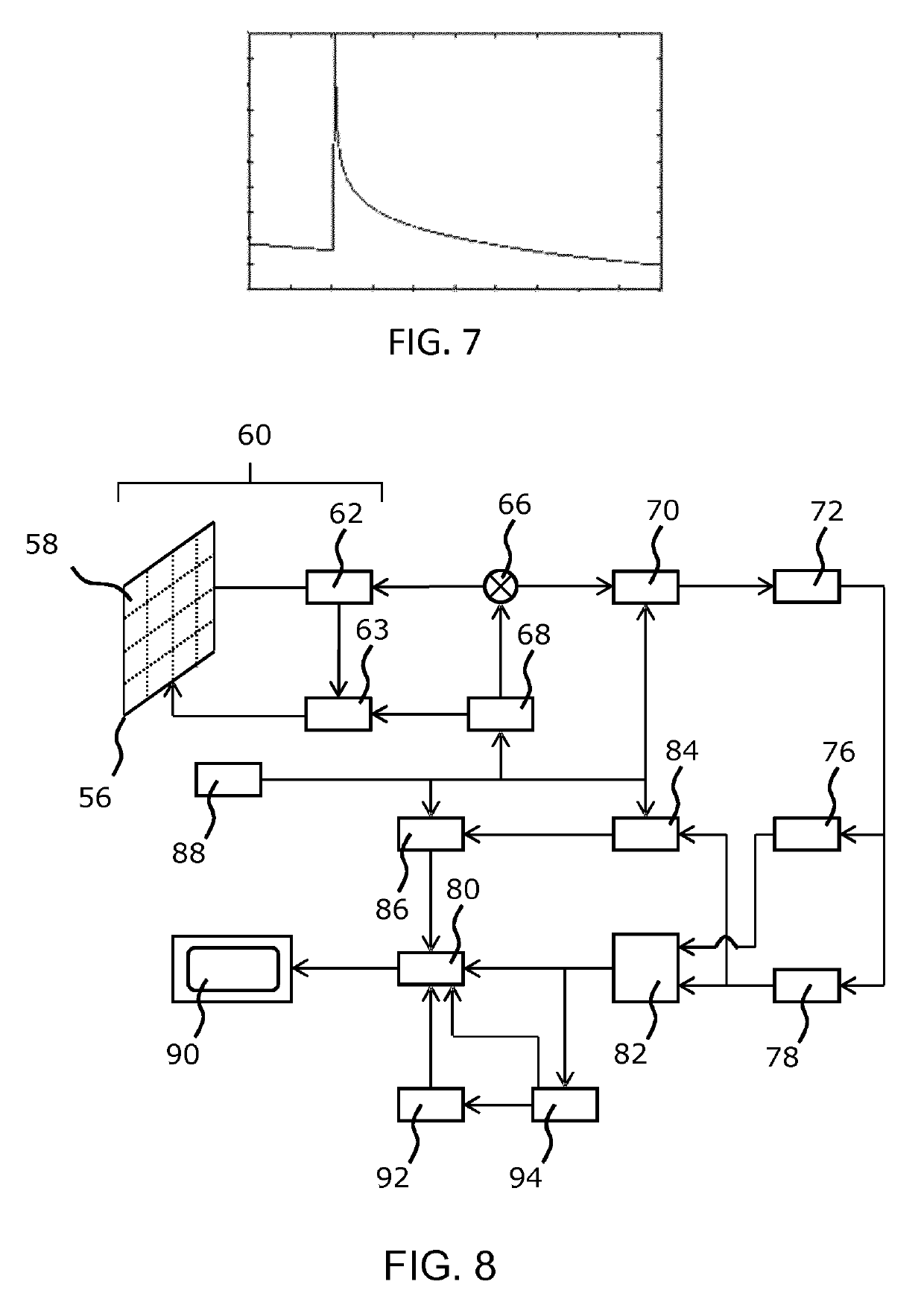
[0045]The feedback signal may be in the form of a current value measured or a voltage parameter measured. Likewise a resistivity or conductivity value may be calculated from voltage and current measurements.

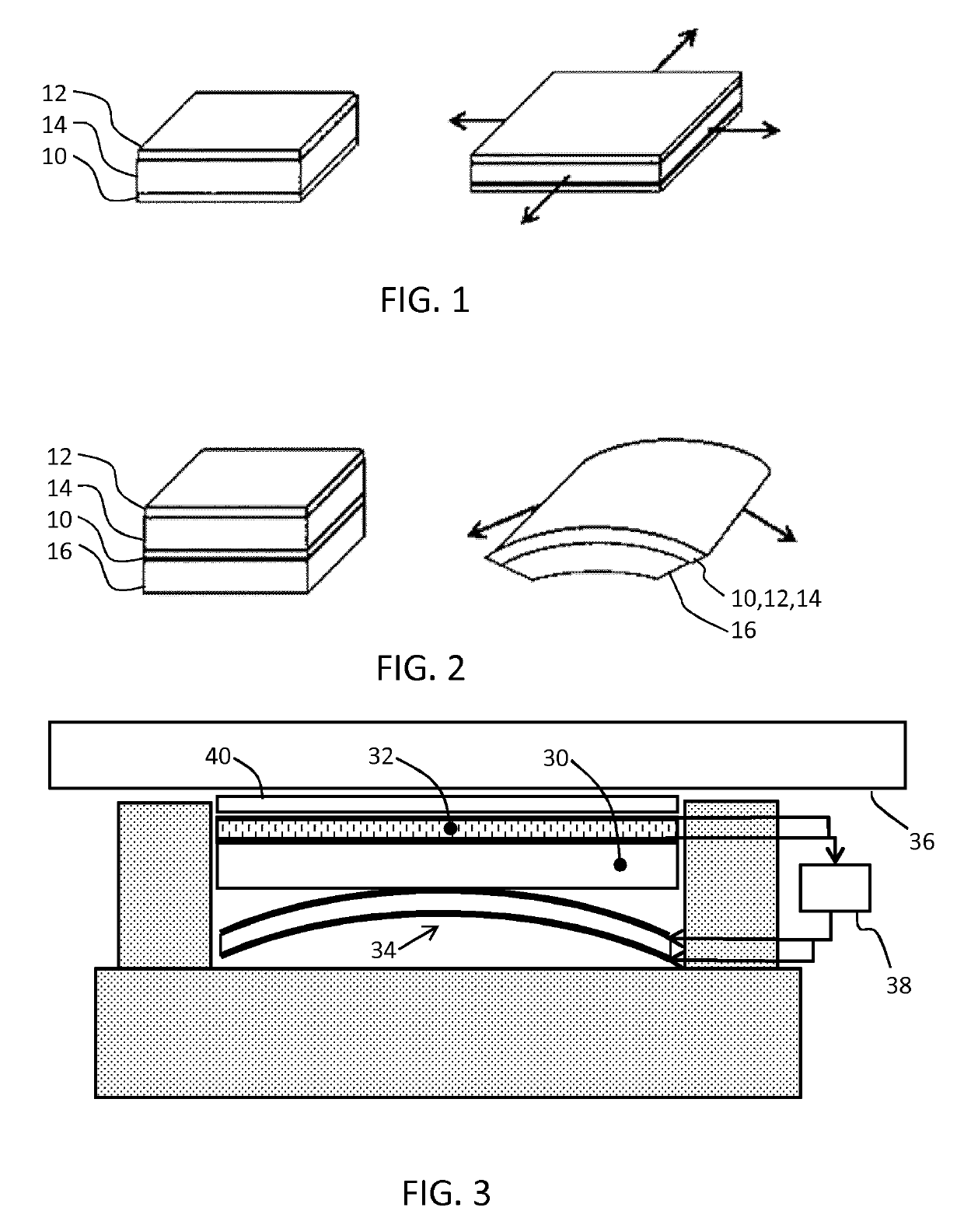
[0046]The invention makes use of an actuator using an electroactive material (EAM), This is a class of materials within the field of electrically responsive materials. When implemented in an actuation device, subjecting an EAM to an electrical drive signal can make them change in size and / or shape. This effect can be used for act...


PUM


Abstract

An ultrasound device comprises a transducer arrangement and an acoustically transmissive window over said arrangement, said window comprising an elastomer layer having conductive particles dispersed in the elastomer, the elastomer layer having a pressure-sensitive conductivity. An electroactive material actuator is provided for biasing the transducer arrangement towards the transmissive window. The electroactive material actuator is controlled in dependence on a measured pressure-sensitive conductivity. In this way, a feedback system is provided for controlling a contact pressure. The device can be implemented with low cost and with low power consumption.

Description

FIELD OF THE INVENTION[0001]The present invention relates to an ultrasound device comprising a transducer arrangement for application to the skin.BACKGROUND OF THE INVENTION[0002]Ultrasound waves find several applications in medicine. One such application is ultrasound imaging, wherein ultrasound waves are emitted by an ultrasound device comprising an array of ultrasound transducers into the body of a patient and echoes of the ultrasound waves are collected by the ultrasound transducers or by dedicated ultrasound receivers and processed to generate an ultrasound image, e.g. a 1D, 2D or 3D ultrasound image. Another application is ultrasound therapy such as high intensity focused ultrasound (HIFU) therapy in which ultrasound beams are generated by an ultrasound device comprising ultrasound transducer element tiles and are focused on diseased tissue. The significant energy deposition at the focus creates local temperatures in the range of about 65° C. to 85° C., which destroys the dece...

Claims


Application Information

Patent Timeline
IPC IPC(8): A61B8/00
CPCA61B8/54A61B8/4483A61B8/4455A61B8/429A61B8/4444A61B8/58
Inventor HAKKENS, FRANCISCUS JOHANNES GERARDUSBELT, HARM JAN WILLEMJOHNSON, MARK THOMASVAN DEN ENDE, DAAN ANTON
Owner KONINKLJIJKE PHILIPS NV
Why Eureka
Try Eureka