Fixing device and image forming apparatus

Active Publication Date: 2012-01-19
KONICA MINOLTA BUSINESS TECH INC
View PDF4 Cites 3 Cited by
  • Summary
  • Abstract
  • Description
  • Claims
  • Application Information

AI Technical Summary

Benefits of technology

[0014]The present invention has been achieved in view of the above problems, and aims to provide a fixing device and an image forming apparatus that realize improvement of the fixing speed and prevention of overheating in the non sheet-passing region at the same time.
[0015]In order to achieve the above aim, a fixing device thermally fixes toner images on recording sheets of various sizes, the fixing device comprising: a conductive heat generating rotational body configured to heat toner images; an excitation coil positioned along a part of an outer circumferential surface of the heat generating rotational body and configured to generate a magnetic flux to heat the heat generating rotational body by electromagnetic induction; and a demagnetization coil positioned close to the excitation coil so as to cover a part of the excitation coil and configured to cancel, when a toner image is being fixed on a smaller-sized recording sheet, a part of the magnetic flux generated by the excitation coil so that overheating is prevented in a region where no recording sheet passes through of the heat generating rotational body, wherein the demagnetization coil has a thickness smaller than a thickness of the excitation coil in an axis direction of the coils.

Problems solved by technology

However, there is a problem that, if output of the excitation coil is increased, overheating of a heating roller in the non sheet-passing region becomes too extreme for practical use. FIG. 10 shows a temperature of the non sheet-passing region when recording sheets of an A6T size (105 [mm]×148.5 [mm]) are passed through in an image forming apparatus that can fix recording sheets of up to an A3 size.
On the other hand, since the recording sheets do not perform cooling of the fixing roller in the non sheet-passing region, a temperature of the fixing roller in the non sheet-passing region becomes higher than in the sheet-passing region.

Method used


Image

  • Fixing device and image forming apparatus
  • Fixing device and image forming apparatus
  • Fixing device and image forming apparatus

Examples


Embodiment Construction

[0028]The following explains an embodiment of the fixing device and the image forming apparatus pertaining to the present invention with reference to the drawings.

[1] Structure of the Image Forming Apparatus

[0029]First, a structure of the image forming apparatus pertaining to a present embodiment will be explained.

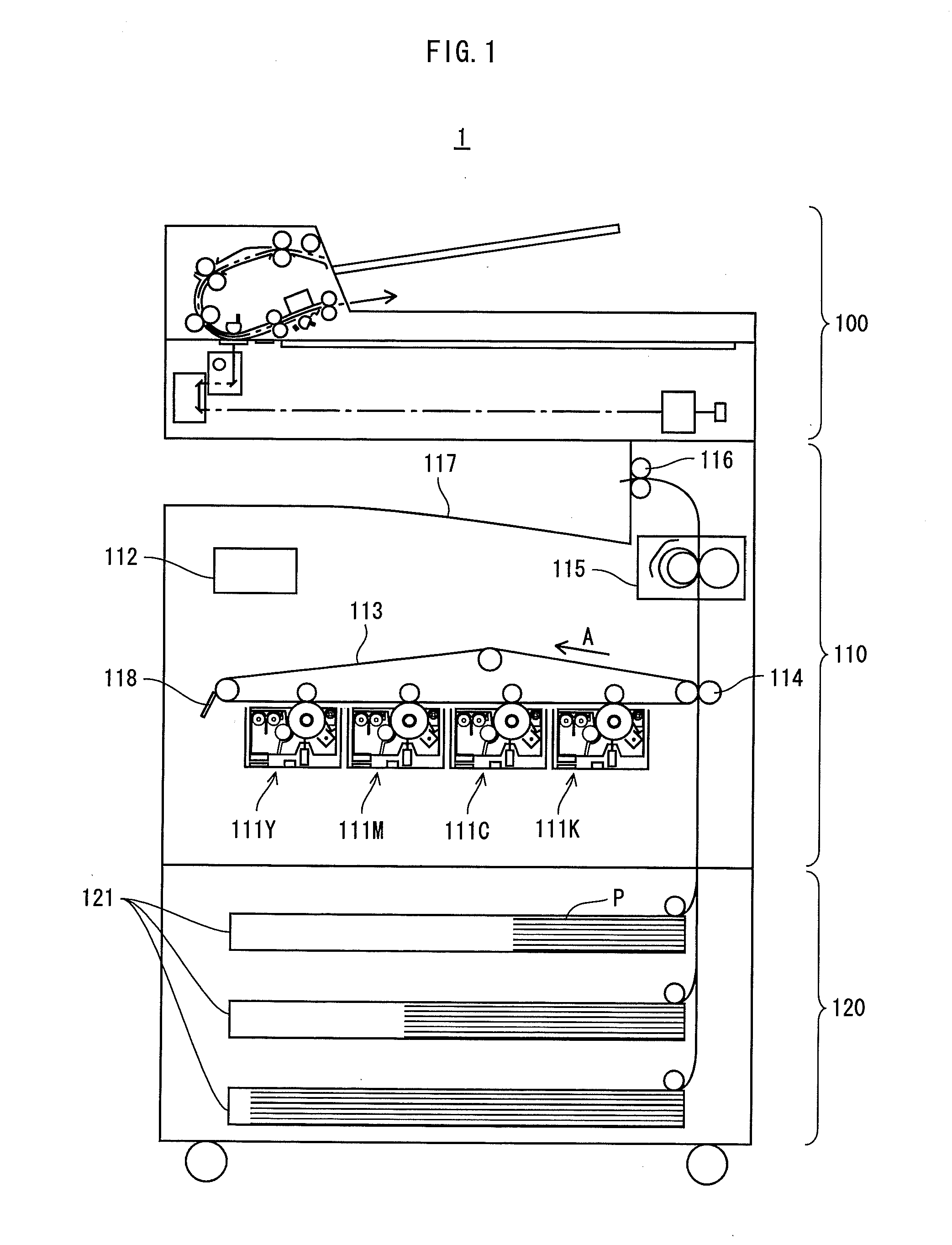
[0030]FIG. 1 shows a main structure of the image forming apparatus pertaining to the present embodiment. As FIG. 1 shows, an image forming apparatus 1 includes a document reader 100, an image forming section 110 and a paper feeder 120. The document reader 100 generates image data by optically reading documents.

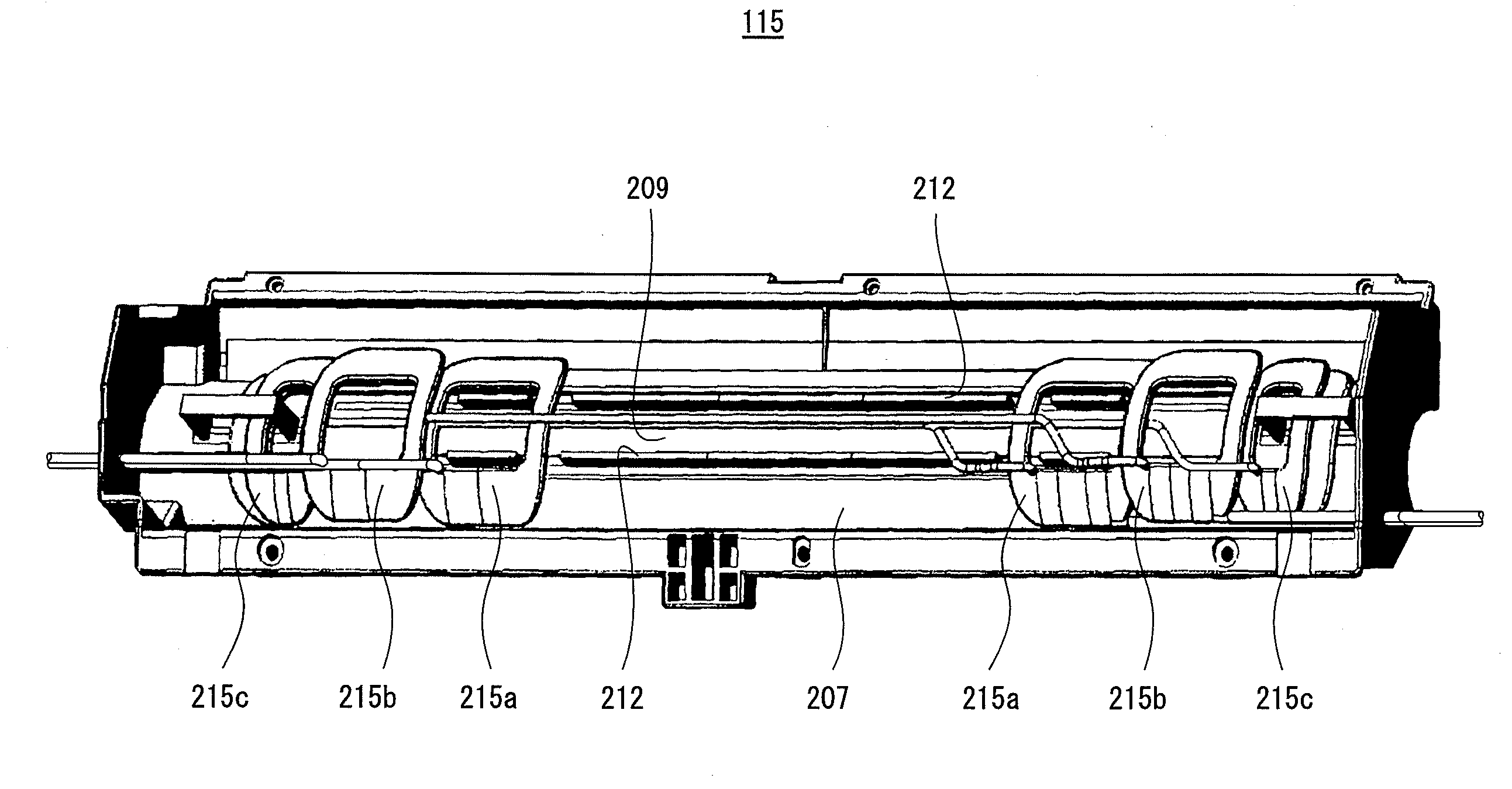
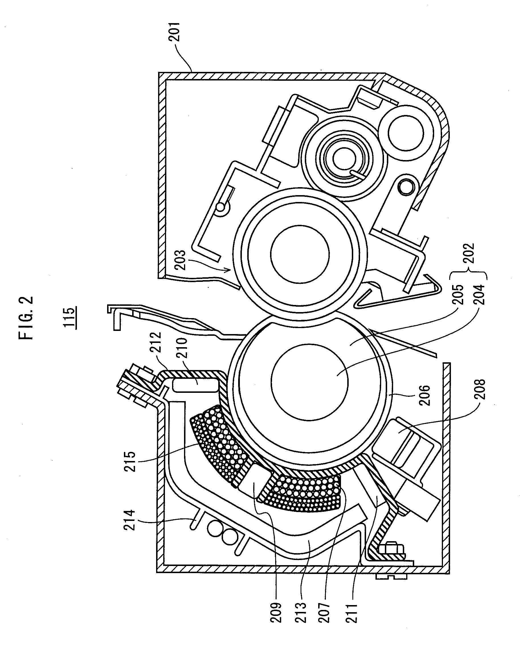
[0031]The image forming section 110 includes image forming units 111Y-111K, a controller 112, an intermediate transfer belt 113, a pair of secondary transfer rollers 114, a fixing device 115, a sheet ejecting roller 116, an ejected-sheet tray 117 and a cleaner 118.

[0032]The image forming units 111Y-111K form toner images in yellow (Y), magenta (M), cyan (C), and blac...


PUM


Abstract

In a fixing device thermally fixing toner images on recording sheets of various sizes, (i) a conductive heat generating rotational body configured to heat toner images, (ii) an excitation coil positioned along a part of an outer circumferential surface of the heat generating rotational body and configured to generate a magnetic flux to heat the heat generating rotational body by electromagnetic induction, and (iii) a demagnetization coil positioned close to the excitation coil so as to cover a part of the excitation coil and configured to cancel, when a toner image is being fixed on a smaller-sized recording sheet, a part of the magnetic flux generated by the excitation coil so that overheating is prevented in a non sheet-passing region, are provided. The demagnetization coil has a thickness smaller than a thickness of the excitation coil in an axis direction of the coils.

Description

[0001]This application is based on an application No. 2010-161472 filed in Japan, the contents of which are hereby incorporated by reference.BACKGROUND OF THE INVENTION[0002](1) Field of the Invention[0003]The present invention relates to an electromagnetic induction-heating type fixing device and an image forming apparatus including such a fixing device, and in particular to a technology for improving a speed for fixing toner images on recording sheets of a small size (hereinafter, referred to as “small-sized recording sheets”) in a fixing device that fixes toner images on recording sheets of various sizes.[0004](2) Related Art[0005]In recent years, in the field of an image forming apparatus, saving of energy has been increasingly required as a part of global warming countermeasures, and accordingly, an induction-heating type fixing device that realizes high energy efficiency has been attracting attention.[0006]An induction-heating type fixing device passes recording sheets through...

Claims


Application Information

Patent Timeline
IPC IPC(8): G03G15/20
CPCG03G2215/2025G03G15/2064G03G15/2053
Inventor KANOU, HIROTAKAKAGAWA, TETSUYA
Owner KONICA MINOLTA BUSINESS TECH INC
Why Eureka
Try Eureka