
Display device with dynamic resolution enhancement

a dynamic resolution and display device technology, applied in the field of optical display systems and devices, can solve the problems of pixel-related limitations on image resolution, insufficient pixel density of electronic displays to directly support the ultimate resolution of human eyes, and user perception of displayed images

Active Publication Date: 2019-10-17
META PLATFORMS TECH LLC
View PDF5 Cites 24 Cited by
  • Summary
  • Abstract
  • Description
  • Claims
  • Application Information

AI Technical Summary

Benefits of technology

The patent describes a display system that uses dynamic image displacement to enhance the resolution and pixel correction of a display. The system includes an electronic display, a display processor, an image shifting device (ISD), and an ISD controller. The display processor receives pixel data from the display processor and presents the images to the user by selectively exciting a pattern of pixel active areas at a native resolution. The ISD shifts the image of the display by a fraction of the display pixel pitch in an image plane. This allows for a higher-resolution input image frame to be divided into subframes, which the display processor then presents to the user. The technical effect of this system is to improve the perceived resolution and quality of the display by enhancing the pixel correction and dynamic resolution enhancement capabilities.

Problems solved by technology

However, in some applications the pixel density of an electronic display may be insufficient to directly support the ultimate resolution of a human eye; for example, rays emitted by neighboring pixels of an electronic display used in a typical head-mounted display (HDM) system may enter the eye at an angle greater than 1′, and the user perception of the displayed image may suffer because of that.
Pixelation artifacts that may be at least partially compensated for using approaches and techniques described herein include pixel-related limitations on image resolution, which may include limitations related to a display pixel density and the appearance of defective pixels in the image.
Neither of these approaches would however improve the resolution of the display for the viewer.

Method used


Image

  • Display device with dynamic resolution enhancement
  • Display device with dynamic resolution enhancement
  • Display device with dynamic resolution enhancement

Examples


Embodiment Construction

[0035]In the following description, for purposes of explanation and not limitation, specific details are set forth, such as particular circuits, circuit components, techniques, etc. in order to provide a thorough understanding of the present invention. However, it will be apparent to one skilled in the art that the present invention may be practiced in other embodiments that depart from these specific details. In other instances, detailed descriptions of well-known methods, devices, and circuits are omitted so as not to obscure the description of the example embodiments. All statements herein reciting principles, aspects, and embodiments of the invention, as well as specific examples thereof, are intended to encompass both structural and functional equivalents thereof. Additionally, it is intended that such equivalents include both currently known equivalents as well as equivalents developed in the future, i.e., any elements developed that perform the same function, regardless of st...


PUM


Abstract

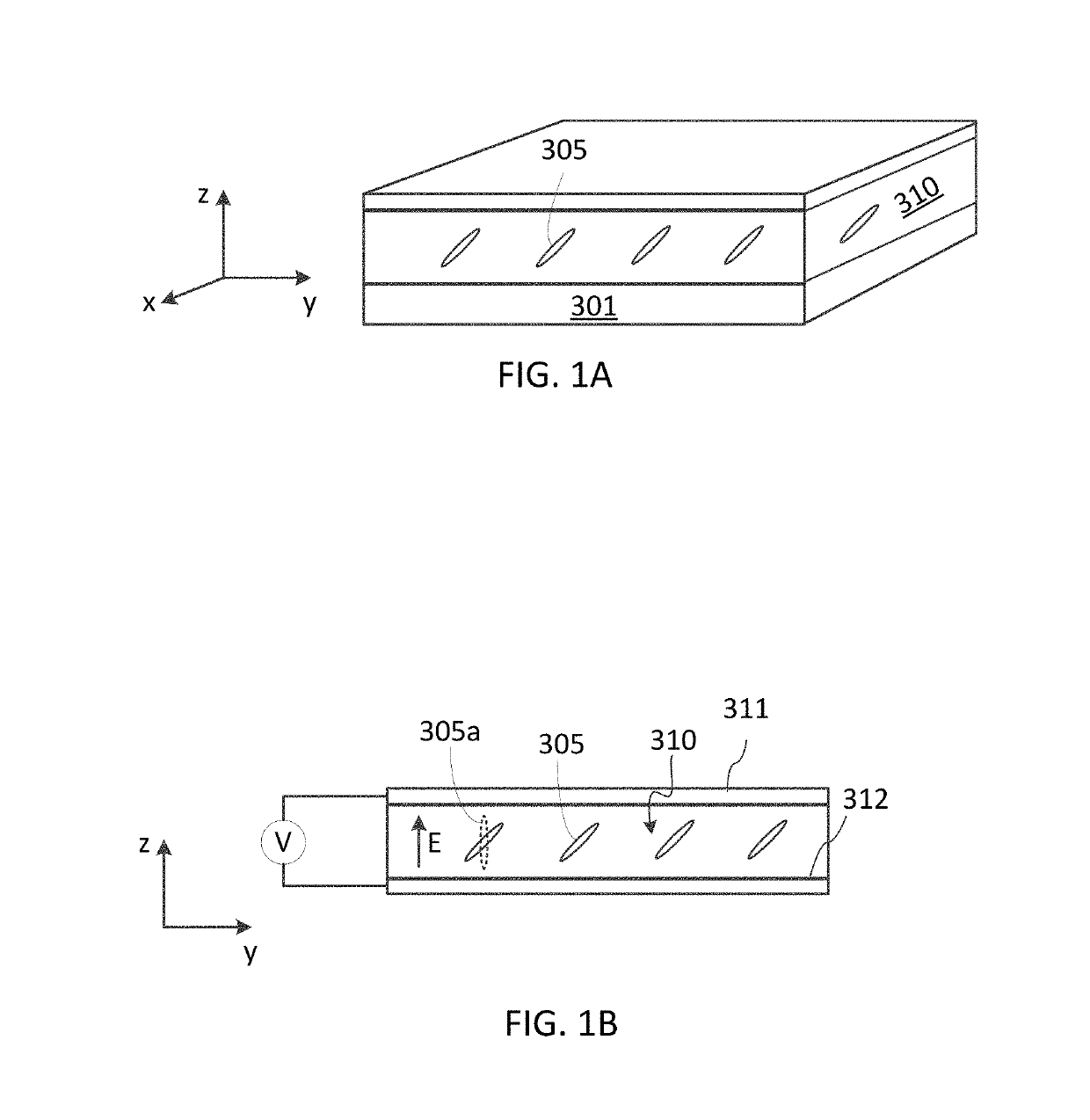
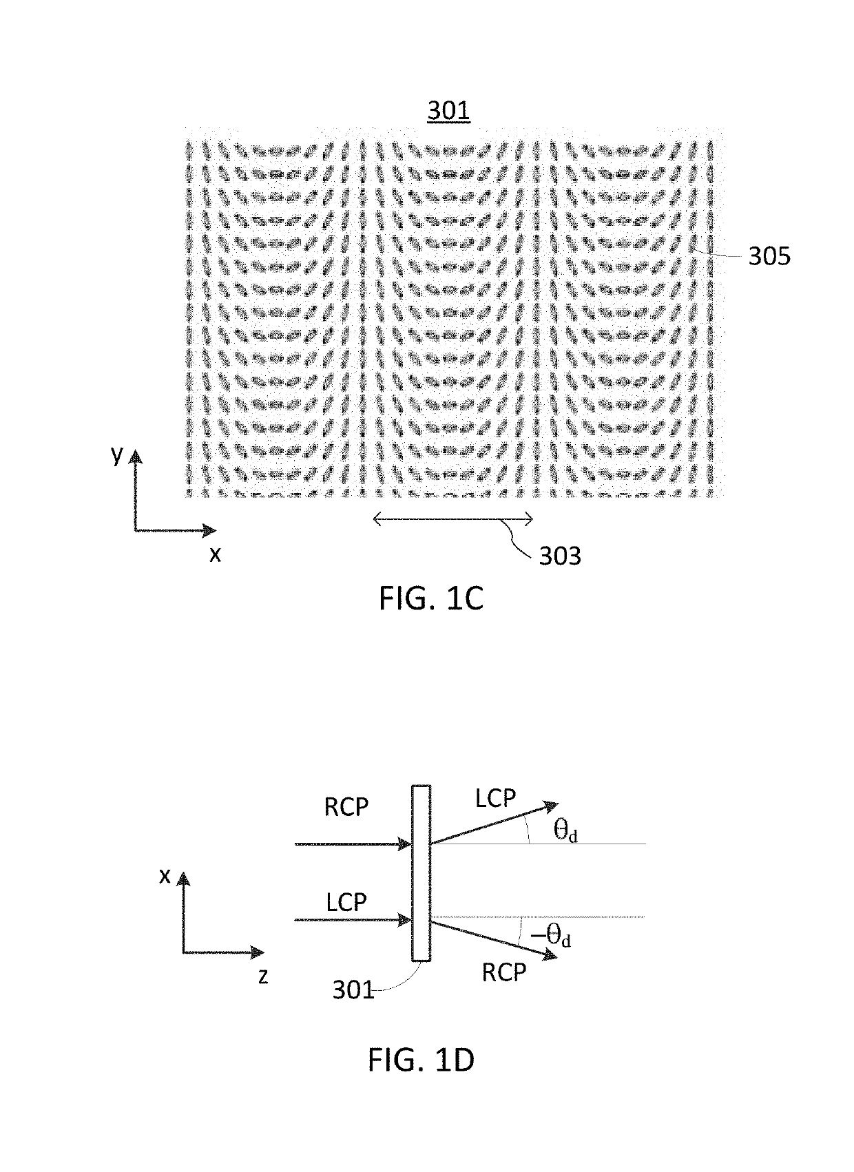
A display apparatus includes an electronic display having a pixel array configured to display a sequence of subframes, and an image shifting electro-optic device that is operable to shift at least a portion of an image of the display pixel array synchronously with displaying the sequence of subframes, so as to form a sequence of offset subframe images for providing an enhanced image resolution and pixel correction in a compound image. The image shifting electro-optic device may include a polarization switch in series with a polarization grating, for shifting image pixels between offset image positions in coordination with displaying consecutive subframes.

Description

CROSS-REFERENCE TO RELATED APPLICATIONS[0001]The present invention claims priority from U.S. Patent Application No. 62 / 658,507 filed Apr. 16, 2018, which is incorporated herein by reference.TECHNICAL FIELD[0002]The present invention generally relates to optical display systems and devices, and in particular to methods and devices for enhancing a resolution of electronic displays.BACKGROUND[0003]Electronic displays typically include arrays of individually addressable pixels. An image is formed by selectively exciting pixels to a various degree of luminesce. The number of pixels per unit area, or pixel density, defines a native resolution of a display. Some display systems have magnification which increases an apparent pixel size. Humans with normal visual acuity, commonly identified as 20 / 20 vision, can distinguish two points separated by an angle of one arc minute (1′), which is the highest resolvable eyesight observed in the foveolar of a human eye. Within about + / −10° of the foveo...

Claims


Application Information

Patent Timeline
IPC IPC(8): G09G5/10
CPCG09G5/10G09G2300/0439G09G2340/04G02B5/30G02B27/017G02B2027/0138G02B2027/014G09G3/007G09G2330/08G09G2330/10G09G2340/0407G09G2340/0435G09G2340/0457G02B26/08
Inventor PENG, FENGLINLU, LUSEARS, JASMINE SORIAGENG, YINGLAM, WAI SZE TIFFANY
Owner META PLATFORMS TECH LLC
Learn More