
Wireless communication device and wireless communication method

Active Publication Date: 2019-10-03
PANASONIC INTELLECTUAL PROPERTY CORP OF AMERICA
View PDF3 Cites 1 Cited by
  • Summary
  • Abstract
  • Description
  • Claims
  • Application Information

AI Technical Summary

Benefits of technology

The patent text is about a technology called "channel bonding" which combines multiple channels to improve data communication in wireless LAN. However, this technology requires the device to constantly monitor each channel, which uses up a lot of electric power. To address this problem, the patent proposes a method to reduce electric power consumption by only sensing the channels that are being used for data communication. This results in more efficient use of battery power, leading to improved operational performance of the device.

Problems solved by technology

However, performing carrier sensing regarding all of multiple channels leads to increased electric power consumption of the wireless communication device.

Method used


Image

  • Wireless communication device and wireless communication method
  • Wireless communication device and wireless communication method
  • Wireless communication device and wireless communication method

Examples


first embodiment

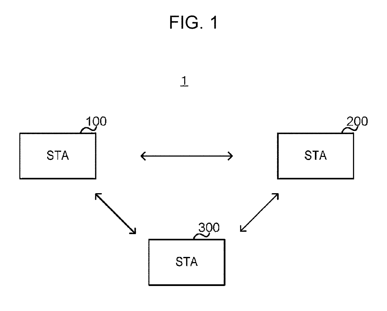
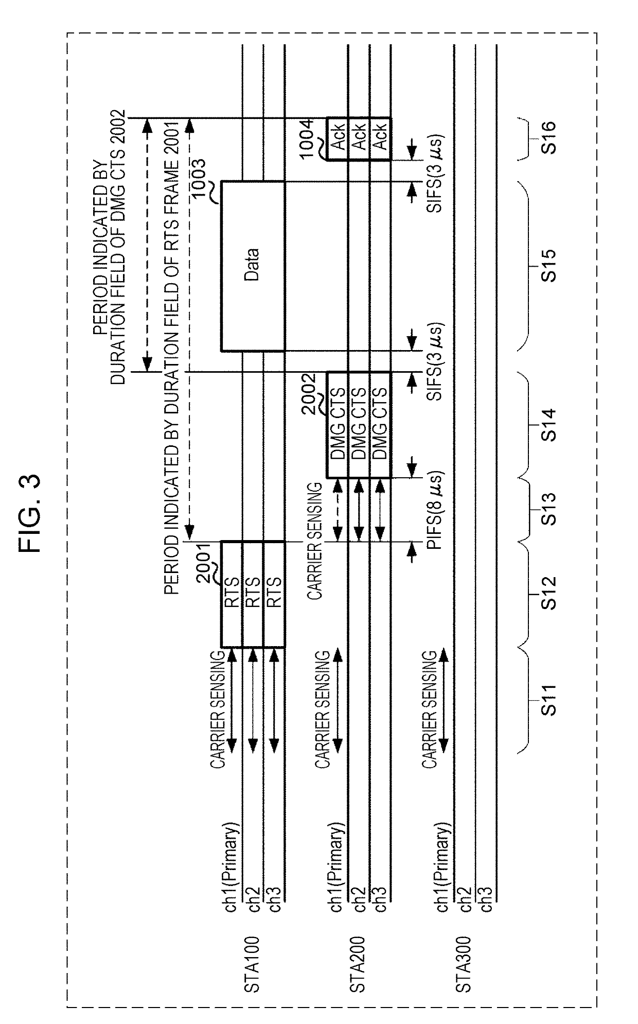
[0057]In a first embodiment, channels for performing carrier sensing are set to part of the multiple channels, thereby reducing electric power consumption of the STAs in standby state. For example, in FIG. 3, the STA 200 (and STA 300) perform carrier sensing regarding a primary channel (ch1 in the example in FIG. 3), and do not perform carrier sensing regarding the remaining channels ch2 and ch3. Accordingly, electric power consumption of the STA 200 (and STA 300) in standby state can be reduced. Note that in the drawings, the primary channel may be abbreviated to “P channel”. One or more channels that are not the P channel may be referred to as “secondary channel (S channel)”.

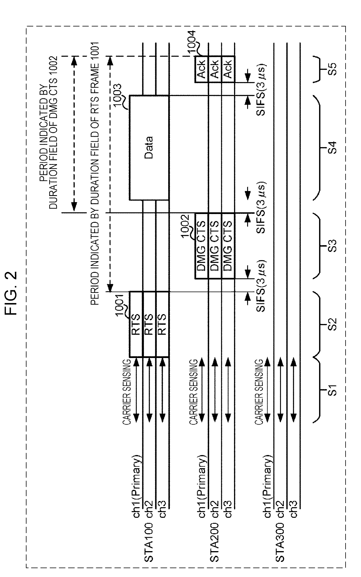
[0058]A data communication example of the wireless communication system 1 according to the first embodiment will be described with reference to FIG. 3. Note that in FIG. 3, the same frames as those exemplified in FIG. 2 are denoted by the same reference numerals in FIG. 3.

Step S11

[0059]The STA 100 that transmi...

second embodiment

[0204]Next, a second embodiment will be described with reference to FIGS. 9 through 11C. FIG. 9 is a diagram illustrating an example of data communication of a wireless communication system 1 according to the second embodiment. An operation example where the STA 100 and another STA 200 perform data communication is illustrated in FIG. 9, in the same way as with FIG. 3. FIG. 10 is a diagram illustrating a format example of a CTS frame 3002. FIGS. 11A through 11C are a flowchart illustrating an operation example of the STA 200 receiving data 3005.

[0205]Note that in the second embodiment, the STA 100, STA 200, and STA 300 may have the same or similar configurations as the configuration exemplified in FIGS. 6A and 6B according to the first embodiment. In other words, the configuration example of the “STA” exemplified in FIGS. 6A and 6B may be shared between the first and second embodiments.

Step S21

[0206]The STA 100 that transmits data 3005 performs carrier sensing of multiple channels (...


PUM


Abstract

A wireless communication device performs first carrier sensing, regarding part of multiple channels that are candidates for receiving a first signal before reception of the first signal. After having received the first signal, the wireless communication device performs second carrier sensing regarding one or more channels, out of the plurality of channels, that are one or more channels corresponding to the channel information included in the first signal, and where at least the first carrier sensing has not been executed, before reception of data signals by transmission of a second signal.

Description

BACKGROUND1. Technical Field[0001]The present disclosure relates to a wireless communication device and a wireless communication method.2. Description of the Related Art[0002]IEEE 802.11 is one of standards related to wireless local area network (LAN), with the IEEE 802.11ad standard and IEEE 802.11ay standard, for example, being included therein (e.g., see IEEE 802.11ad-2012 and IEEE 802.11-16 / 1482r01 Carrier Sense for Multi-Channel Allocation, (online), November 2016, (searched Nov. 17, 2017), Internet <URL:https: / / mentor.ieee.org / 802.11 / dcn / 16 / 11-16-1482-01-00ay-carrier-sense-for-multi-channel-allocation.pptx>). Note that “IEEE” is short for “Institute of Electrical and Electronics Engineers”. Hereinafter, the “IEEE 802.11ad standard” may be abbreviated to “11 ad standard”, and the “IEEE 802.11 ay standard” may be abbreviated to “11 ay standard”.SUMMARY[0003]Using a communication technology called “channel bonding”, where data communication is performed by aggregating multi...

Claims


Application Information

Patent Timeline
IPC IPC(8): H04W74/08H04W72/04
CPCH04W74/0808H04W72/0406H04W84/12H04W74/0816Y02D30/70H04W72/20
Inventor WEE, YAO HUANG GAIUSMOTOZUKA, HIROYUKIIRIE, MASATAKASAKAMOTO, TAKENORI
Owner PANASONIC INTELLECTUAL PROPERTY CORP OF AMERICA
Learn More