Gasket

Inactive Publication Date: 2019-10-03
AFGLOBAL UK LTD
View PDF5 Cites 0 Cited by
  • Summary
  • Abstract
  • Description
  • Claims
  • Application Information

AI Technical Summary

Benefits of technology

The patent text explains that using a gasket with a softer hardness than the seal faces of the mating hubs helps improve how well the gasket seals. This is because any particles present during assembly can be forced into the softer gasket, which can then be easily removed from underground. This reduces the risk of damaging the permanently installed hubs.

Problems solved by technology

A number of difference gaskets have been proposed for subsea use, such as AX style gaskets, however these have limited deepwater resistance.

Method used


Image

  • Gasket
  • Gasket
  • Gasket

Examples


Embodiment Construction

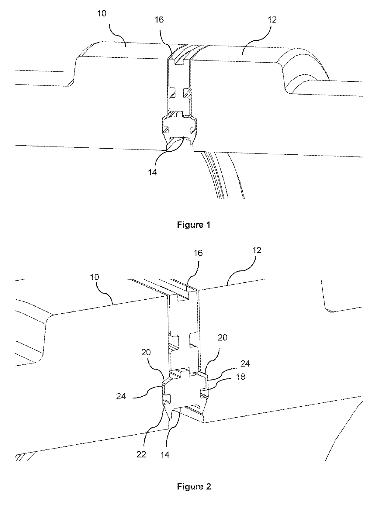
[0042]Referring to FIG. 1 the joint comprises first and second tubular members 10, 12 in the form of flanged hubs, a gasket 14 and a seal plate 16. The sealing assembly engages with the flanged hubs of the tubular members, with the gasket engaging via a recess 18 in the end faces of the hubs. The hubs of the tubular members are profiled to cooperate with the gasket, and each hub comprise a recess defined by outer (top) 20 and inner 22 (bottom) side walls that taper inwards from the flanged face to the base 24 of the recess, as shown in the FIGS. 1 and 2.

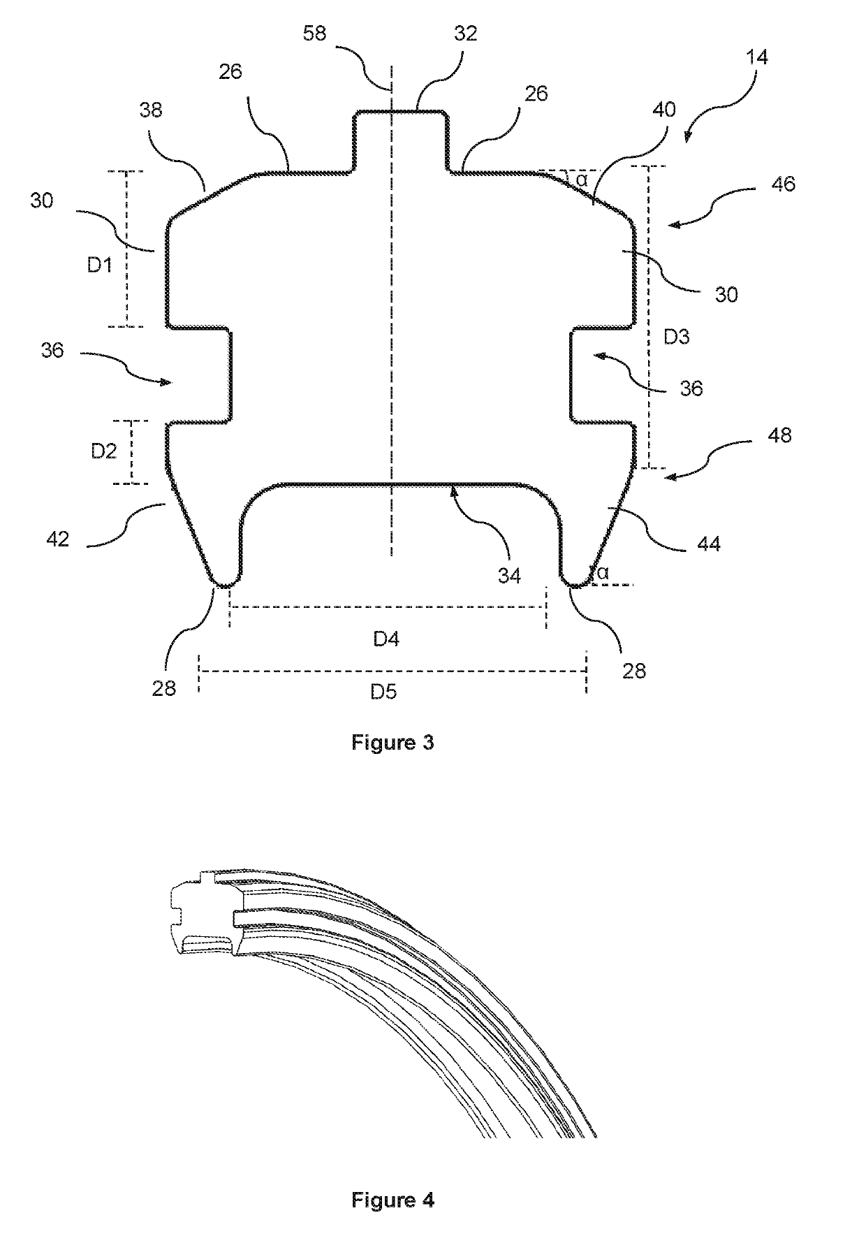
[0043]Referring to FIG. 3, the annular gasket 14 comprises an outer (top) circumferential surface 26 and an inner circumferential (bottom) surface 28 and opposing side surfaces 30. An annular rib 32 extends radially from the outer surface and an annular channel 34 is formed in the inner surface. Each side surface comprises an annular recess 36 circumferentially extending around the side of the annular gasket. The outer surface 26 is ...


PUM


Abstract

Provided is a seal ring (14), such as a gasket, for use in connecting the end of a first conduit to the end of second conduit or other installation, in subsea environments. A metal gasket for providing a sealing connection between first and second tubular members comprises: two opposing side surfaces (30), each side surface comprising an annular recess (36) for receiving an elastomeric annular sealing member, an outer circumferential surface (26) comprising an annular rib portion (32), and an inner circumferential surface (28) comprising an annular channel (34). The gasket further comprises a first pair of annular tapered surfaces (38, 40) between the side surfaces and the outer circumferential surface; and a second pair of annular tapered surfaces (42, 44) between the side surfaces and the inner circumferential surface.

Description

[0001]This application claims the benefit of priority to United Kingdom Patent Application Serial No. 1613459.5, filed Aug. 4, 2016, hereby incorporated by reference in its entirety.[0002]This invention relates to a seal ring for use in the connection of conduits and the like in a subsea environment.BACKGROUND[0003]When connecting adjacent sections of fluid flow conduits seal rings, such as gaskets, are typically interposed at the interface of adjacent connecting flanged conduits, which are then bolted or clamped together.[0004]The annular metallic seal ring, provided at the interface between the flanged hubs of the conduits, prevents fluid leaking out of the fluid flow path. In a subsea deepwater environment the seal may have to withstand internal and / or external pressures equivalent to depths in the order of 5000 m or above of sea water without leakage of fluid at the interface.[0005]A number of difference gaskets have been proposed for subsea use, such as AX style gaskets, howeve...

Claims


Application Information

Patent Timeline
IPC IPC(8): F16J15/08F16J15/06F16L17/08
CPCF16L17/08F16J15/062F16J15/061F16J15/0881F16L23/20F16L23/18F16J15/08F16L23/00
Inventor SCHNEIDER, KIEREN
Owner AFGLOBAL UK LTD
Why Eureka
Try Eureka