
Coil component and coil device

a coil device and coil component technology, applied in the direction of transformer/inductance coil/winding/connection, transformer/inductance details, electrical apparatus, etc., can solve the problems of difficult downsizing of coil devices and great deterioration of magnetic properties, and achieve the effect of easy avoiding mutual interference and difficulty in downsizing coil devices

Active Publication Date: 2019-09-19
SUMIDA CORP
View PDF0 Cites 0 Cited by
  • Summary
  • Abstract
  • Description
  • Claims
  • Application Information

AI Technical Summary

Benefits of technology

The present invention provides a coil component and a coil device that can reduce the gap between the coil elements, make the device smaller, and prevent deterioration in magnetic properties. The interconnection part connecting the coil elements is designed to prevent twisting and catching, making it easier to downsize the device. The coil component and device have a linear face without twisting that can be formed easily. The intermediate part of the interconnection part is placed parallel to the plane that is in parallel to the disposing direction and axial direction of the coil elements, and a long screw can be provided in parallel to the linear face of the intermediate part to avoid mutual interference.

Problems solved by technology

Therefore, it is difficult to downsize the coil device.
Expansion of the gap between the two coil elements even by several millimeters, for example, results in a great deterioration in the magnetic property, so that it is desired to employ a structure causing no such twisting of the flat wire used for connecting the coil elements.

Method used


Image

  • Coil component and coil device
  • Coil component and coil device
  • Coil component and coil device

Examples


embodiment 1

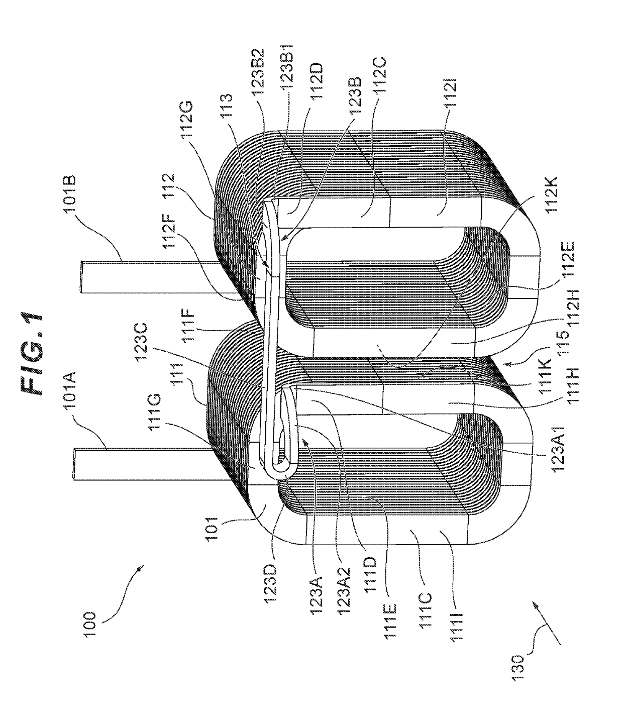
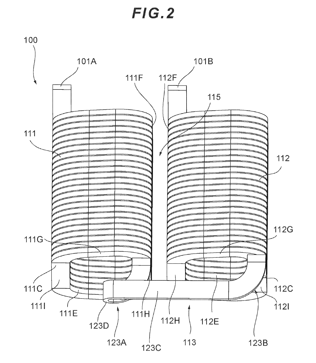
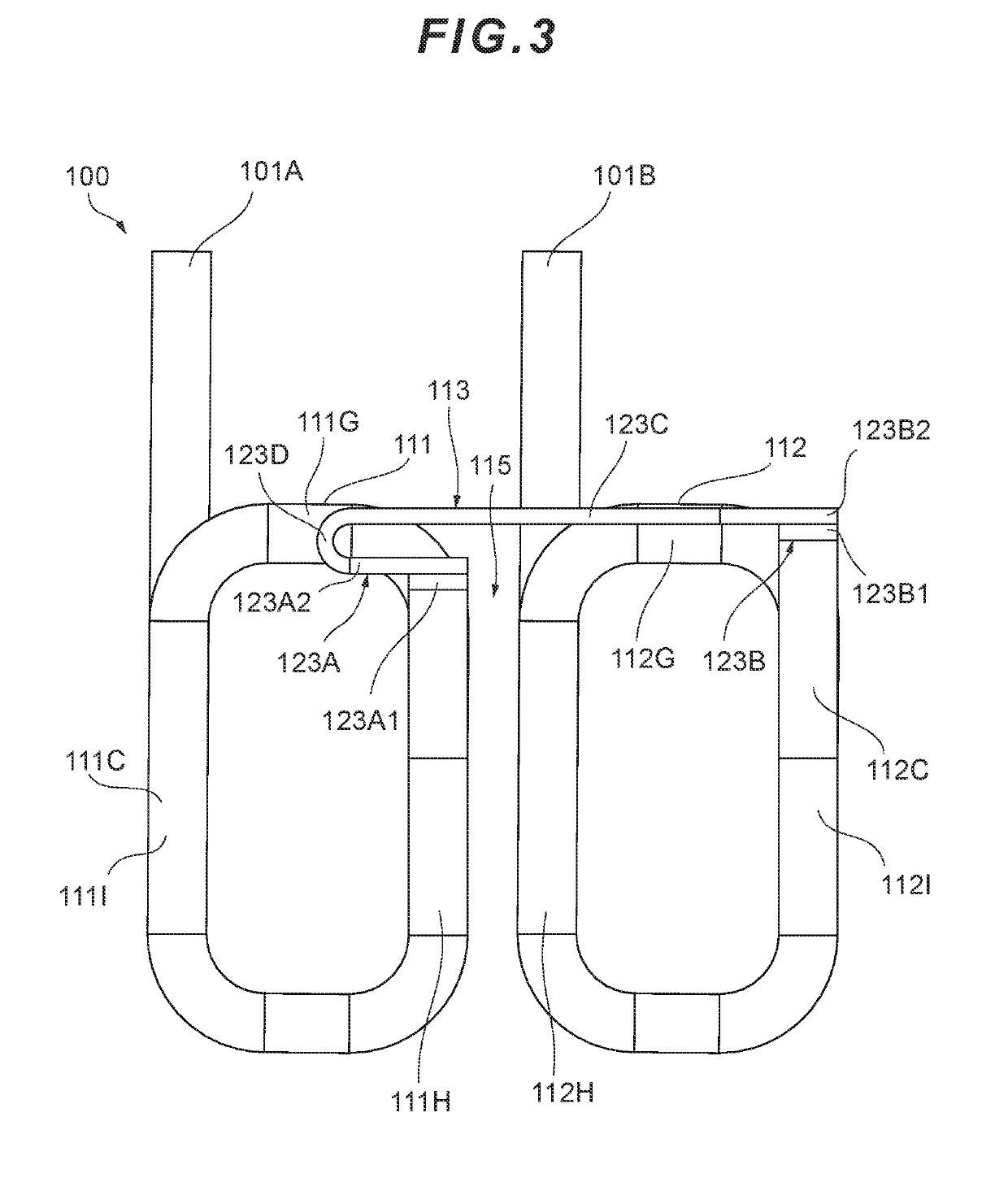
[0040]FIG. 1 is a perspective view showing a state of a coil component according to a first embodiment of the present invention viewed from a front side. FIG. 2 is a perspective view showing a state of the coil component according to the first embodiment shown in FIG. 1 viewed from above. FIG. 3 is a front view showing a state of the coil component according to the first embodiment shown in FIG. 1 viewed from the front side.

[0041]As shown in FIG. 1, a coil component 100 of the first embodiment is formed by winding and laminating a single flat wire 101 in one direction with edgewise-winding between one end portion 101A and another end portion 101B as connection terminals, and bending the wound and laminated coil into two at a prescribed position (normally at substantially middle position) to provide a first coil element 111 and a second coil element 112 each formed in an angular-tubular shape and disposed in parallel and to provide an interconnection part 113 for connecting the both ...

embodiment 2

[0065]In this second embodiment, there are many members common to the members of the first embodiment described above. Therefore, reference numerals acquired by adding 100 to the reference numerals of the members of the first embodiment are applied to such common members, and detailed explanations of such members are to be omitted.

[0066]That is, as shown in FIG. 9, a coil component 200 of the second embodiment is similar to the coil component 100 of the first embodiment described above in respect that the coil component 200 is configured by winding and laminating a single flat wire 201 with edgewise-winding between one end portion 201A and another end portion 201B as connection terminals, and bending the wound and laminated coil into two at a prescribed position (normally at substantially middle position) to provide a first coil element 211 and a second coil element 212 each formed in an angular-tubular shape and disposed in parallel and to provide an interconnection part 213 for co...


PUM

PropertyMeasurementUnit
angleaaaaaaaaaa
magneticaaaaaaaaaa
areasaaaaaaaaaa

Abstract

Provided is a coil component 100 including a first coil element 111 and a second coil element 112 each formed in an angular-tubular shape and disposed in parallel, and an interconnection part 113 for connecting the both coil elements 111, 112. The interconnection part 113 is configured with a first connecting part 123A, a second connecting part 123B, an intermediate part 123C, and an inverted part 123D. The first connecting part 123A is configured with a flatwise-bending portion 123A1 and an edgewise-winding portion 123A2. The second connecting part 123B is configured with a flatwise-bending portion 123B1 and an edgewise-winding portion 123B2. The intermediate part 123C is provided to extend over a gap part 115 between the second coil element 112 and the first coil element 111 on a front end-face side without being twisted.

Description

RELATED APPLICATION[0001]This application claims the priority of Japanese Patent Application No. 2018-046751 filed on Mar. 14, 2018, which is incorporated herein by reference.BACKGROUND OF THE INVENTIONField of the Invention[0002]The present invention relates to a coil component and a coil device used for inverter circuits and various motors and the like used for automobiles and the like and, more specifically, to a coil component configured with two angular-tubular shaped laminated coils formed with a single flat wire and provided adjacent to each other and to a coil device using the same.Description of the Prior Art[0003]A coil component such as a reactor can generate an inductance with a structure where a winding coil is wound around a magnetic core.[0004]There are various types known as the reactors depending on the purpose of use from a type of a large capacitance used for a power transmission system to a component of a communication apparatus.[0005]Incidentally, as the reactor...

Claims


Application Information

Patent Timeline
Patent Type & Authority Applications(United States)
IPC IPC(8): H01F27/30H01F27/28
CPCH01F27/30H01F27/2823H01F27/28H01F27/2852H01F27/306H01F41/061
Inventor KAWASHIMA, HIROSHI
Owner SUMIDA CORP
Learn More