
Expanding Interbody Spacers

a technology of expanding interbody and spacer, which is applied in the field of expanding interbody spacers, can solve the problems of existing spacers that may induce subsidence, existing spacers that cannot be expanded, and are difficult to place large, so as to reduce rasping requirements and localized overloading, expand interbody technology, and improve the effect of expanding interbody technology

Active Publication Date: 2019-09-12
NEXUS SPINE L L C
View PDF0 Cites 4 Cited by
  • Summary
  • Abstract
  • Description
  • Claims
  • Application Information

AI Technical Summary

Benefits of technology

The invention is an improved version of expanding interbody technology that solves problems with current interbody spacers. It uses designs and materials that allow for better conformance with the vertebral endplates, reducing rasping requirements and subsidence. The technology also matches the stiffness of bone and allows for better load sharing, encouraging bone formation and reduced stress shielding. The expansion mechanism exerts a controlled force on the spine, minimizing stress shielding and endplate fracture. The expandable interbody spacer reduces carrying costs and the need for trialing. Overall, the technology improves spine stability and reduces complications.

Problems solved by technology

In many instances, surgical access to the interbody space is limited, and it therefore becomes difficult to place large, supportive interbody spacers through the limited access sites.
Existing expanding interbody spacers have remaining problems, however.
Existing spacers may induce subsidence through excessive stiffness, localized over-loading, or by requiring procedural weakening of the vertebral endplates (e.g., by excessive rasping).
Finally, most existing spacers do not have an optimal pore size for bone on-growth and bone ingrowth or through-growth.

Method used


Image

  • Expanding Interbody Spacers
  • Expanding Interbody Spacers
  • Expanding Interbody Spacers

Examples


Embodiment Construction

[0057]A description of embodiments of the present invention will now be given with reference to the Figures. It is expected that the present invention may take many other forms and shapes, hence the following disclosure is intended to be illustrative and not limiting, and the scope of the invention should be determined by reference to the appended claims.

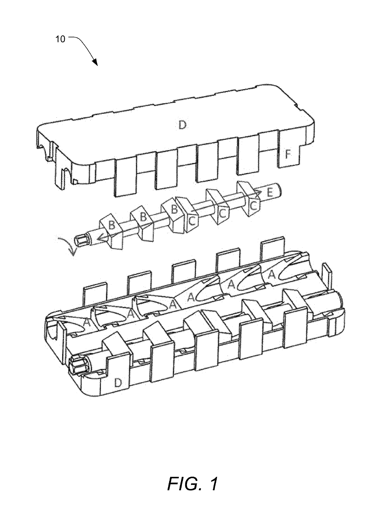
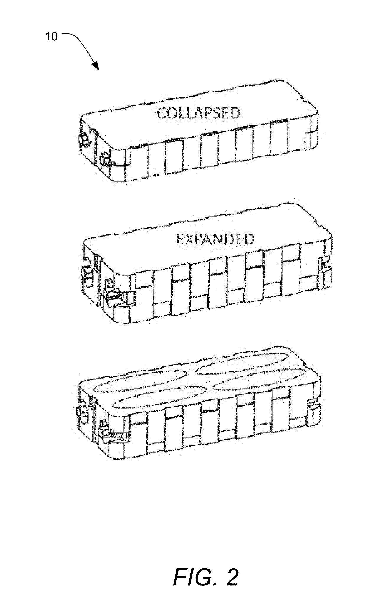
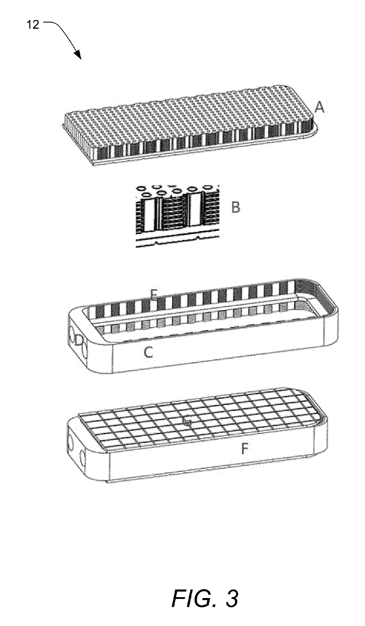
[0058]Embodiments of the invention provide improved expanding interbody technology that overcomes many of the problems with current interbody spacers. Expanding interbody technology is improved by the use of designs and / or materials that allow for improved conformance of the interbody spacer to the vertebral endplates, thereby reducing rasping requirements and localized overloading that may lead to subsidence. Expanding interbody technology is also improved by the use of designs and / or materials that better match the stiffness of bone and allow for better load sharing. This encourages better bone formation and reduced stress shieldi...


PUM


Abstract

An expandable interbody spacer includes a first endplate surface located on a first side of the spacer and adapted to contact a vertebral endplate surface of a first vertebral body, a second endplate surface located on a second, opposed, side of the spacer and adapted to contact a vertebral endplate surface of a second, opposed, vertebral body and an expansion mechanism adapted to selectively apply a distracting force between the first endplate surface and the second endplate surface, whereby actuation of the expansion mechanism causes the spacer to transition between a compressed insertion configuration to an expanded fusion configuration. The spacer also includes one or more of a deformable surface, a porosity to promote bone on-growth or through-growth, a stiffness substantially equivalent to cortical bone, and structure distributing loads through the spacer substantially without transferring the loads through higher-stiffness structures.

Description

CROSS-REFERENCE TO RELATED APPLICATIONS[0001]This application claims the benefit of U.S. Provisional Application No. 62 / 640,555, filed Mar. 8, 2018, U.S. Provisional Application No. 62 / 736,924, filed Sep. 26, 2018, and U.S. Provisional Application No. 62 / 751,432, filed Oct. 26, 2018, each of which is incorporated herein by reference in its entirety for all it discloses.BACKGROUND OF THE INVENTION1. Field of the Invention[0002]The present invention relates to spinal implants, and more particularly to expanding interbody spacers for use in spinal fusion procedures.2. Background and Related Art[0003]In certain spinal fusion procedures, an interbody spacer is used to support and stabilize the spine while the fusion occurs. There are different types of procedures in which different types of access are used to place the interbody spacer. These types of access include transforaminal lumbar interbody fusion (TILF), posterior lumbar interbody fusion (PLIF) and lateral lumbar interbody fusion...

Claims


Application Information

Patent Timeline
Patent Type & Authority Applications(United States)
IPC IPC(8): A61F2/44A61F2/46
CPCA61F2002/30556A61F2002/4615A61F2002/30784A61F2002/3093A61F2002/30579A61F2/4611A61F2002/30476A61F2/447A61F2002/30622A61F2002/3007
Inventor MANWILL, DANIELHALVERSON, PETERHAWKES, DAVID
Owner NEXUS SPINE L L C
Learn More