
Substrate processing method and apparatus

a processing method and substrate technology, applied in the direction of coatings, chemical vapor deposition coatings, electric discharge tubes, etc., can solve the problems of uneven trimming and inability to ensure the uniformity of critical dimensions

Active Publication Date: 2019-08-22
ASM IP HLDG BV
View PDF26 Cites 212 Cited by
  • Summary
  • Abstract
  • Description
  • Claims
  • Application Information

AI Technical Summary

Benefits of technology

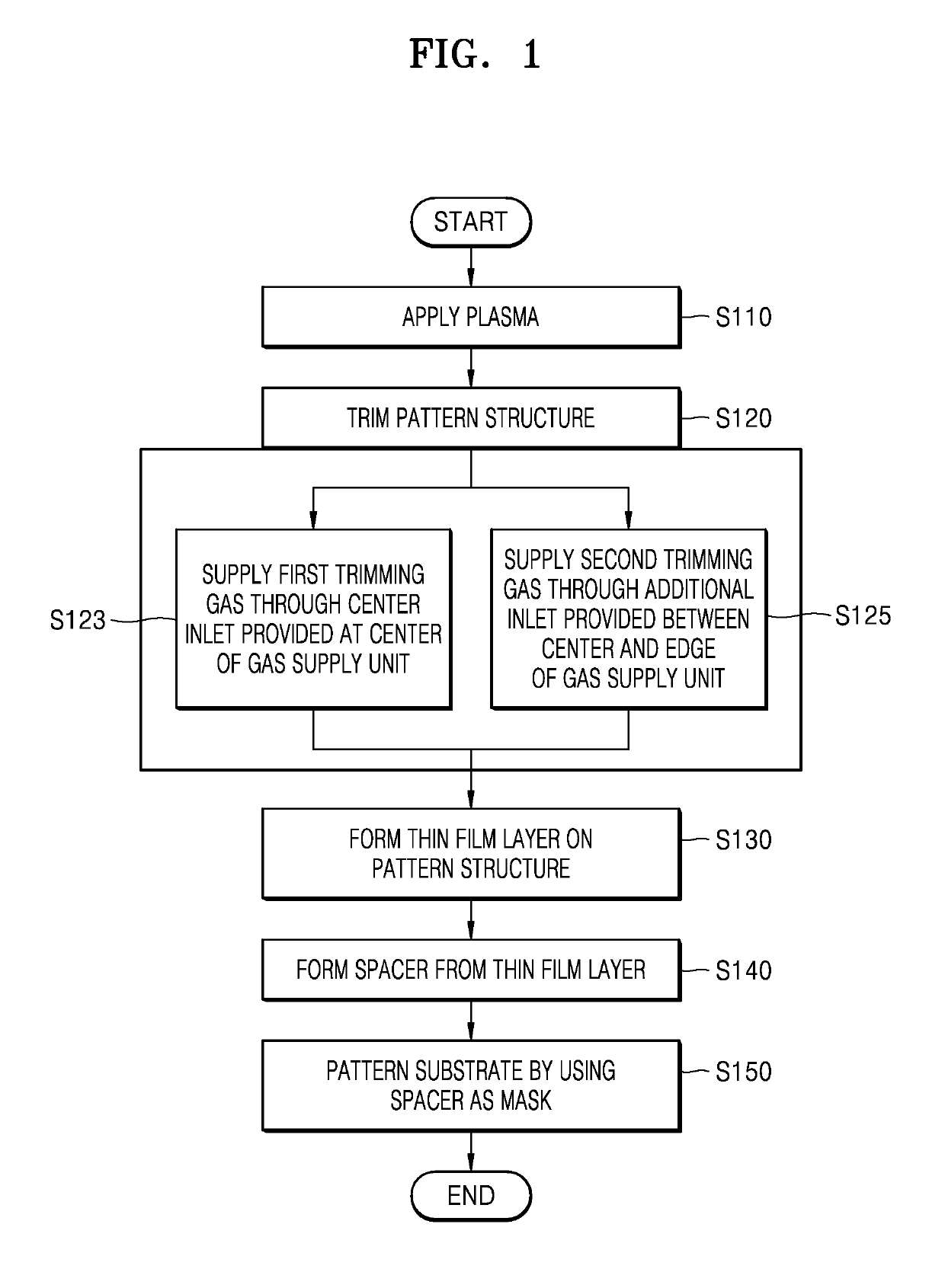
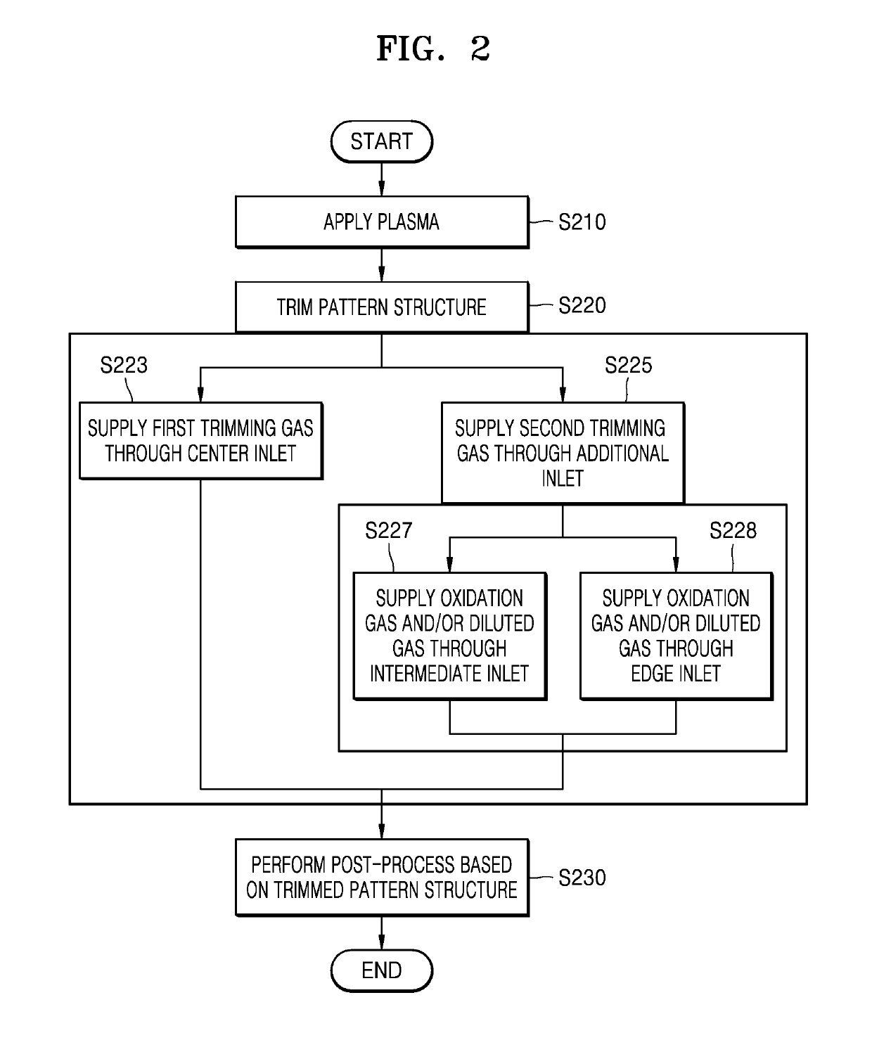
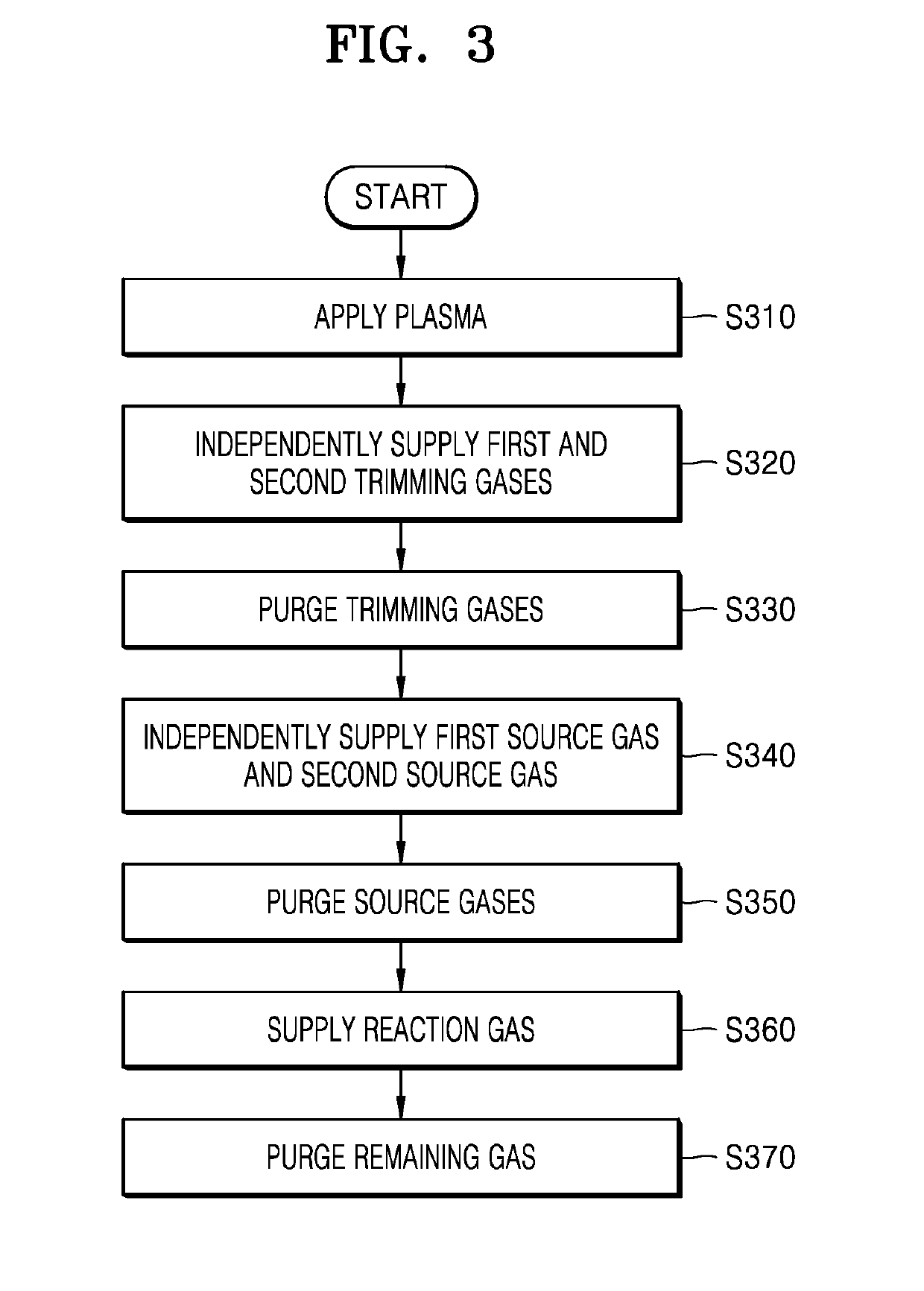
The patent describes a method and apparatus for processing a substrate by applying plasma and trimming a pattern structure on the substrate. The method includes using a first trimming gas and a second trimming gas to independently control the trimming of the pattern structure. The apparatus includes a gas channel with a center gas inlet and an additional gas inlet, which allows for localized control of processing. The method and apparatus can be used to form a thin film layer on the pattern structure and perform a patterning process using the thin film layer as a mask. The technical effects include improved precision and control during pattern structure trimming and the formation of a thin film layer for patterning.

Problems solved by technology

Moreover, according to the trimming technique of the related art, the trimming may not be achieved evenly throughout the entire substrate, and accordingly, uniformity in the critical dimensions (CD) may not be guaranteed.

Method used


Image

  • Substrate processing method and apparatus
  • Substrate processing method and apparatus
  • Substrate processing method and apparatus

Examples


embodiment 1-1

[0062]A gas supply apparatus was designed to include a center gas inlet and an additional gas inlet, and the additional gas inlet includes a first additional gas inlet (middle gas inlet) and a second additional gas inlet (edge gas inlet) (see FIG. 12). A flow rate of O2 gas supplied through the center gas inlet was set as 300 sccm. A flow rate of O2 gas supplied through the middle gas inlet was set as 250 sccm, and a flow rate of Ar gas supplied through the edge gas inlet was set as 1450 sccm. A pressure in the chamber was 240 Pa, and HRF was set as 25 W. In this case, as shown in FIG. 24, a ratio between the trimming amount at the edge and the trimming amount at the center was 1.1 to 1.2, but a difference between the trimming amount at a left edge and the trimming amount at a right edge (about 0.5) was observed.

embodiment 1-2

[0063]A gas supply apparatus was designed to include a center gas inlet and an additional gas inlet, and the additional gas inlet includes two pairs of first additional gas inlets (middle gas inlets) and a second additional gas inlet (edge gas inlet) (see FIG. 13). Also, the above two pairs were symmetrically arranged by an angle of 180. Except for the change in the gas supply apparatus, the photoresist film on the wafer was trimmed under the same condition as that of the embodiment 1-1. When comparing with the embodiment 1-1, as shown in FIG. 25, a ratio between the trimming amount at the edge and the trimming amount at the center was 1.1 and the trimming amounts at the left edge and the right edge were almost the same as each other.

embodiment 2

[0064]The gas supply apparatus used in the embodiment 2 was the same as that used in the embodiment 1-2, and the embodiment 2 is different from the embodiment 1-2 in that O2 gas was supplied through the center gas inlet, the middle gas inlet, and the edge gas inlet. Also, conditions on a flow rate of the gas were also changed in the embodiment 2, in addition to the kind of the gas. A flow rate of O2 gas supplied through the center gas inlet was set as 1920 sccm, a flow rate of O2 gas supplied through the middle gas inlet was set as 40 sccm, and a flow rate of O2 gas supplied through the edge gas inlet was set as 40 sccm. In this case, as shown in FIG. 26, a ratio between the trimming amount at the edge and the trimming amount at the center was 1, that is, the trimming amounts were equal to each other (see Example 2 of FIG. 26). That is, under the conditions of the embodiment 2, the trimming was evenly achieved at the center and the edge of the wafer.


PUM

PropertyMeasurementUnit
Angleaaaaaaaaaa
Angleaaaaaaaaaa
Thicknessaaaaaaaaaa

Abstract

Provided are a substrate processing apparatus and a substrate processing method capable of achieving uniform trimming throughout an entire surface of a substrate. The substrate processing apparatus includes a gas channel including a center gas inlet and an additional gas inlet spaced apart from the center gas inlet, and a shower plate including a plurality of holes connected to the center gas inlet and the additional gas inlet, wherein a gas flow channel is formed having a clearance defined by a lower surface of the gas channel and an upper surface of the shower plate, the lower surface and the upper surface being substantially parallel.

Description

CROSS-REFERENCE TO RELATED APPLICATION[0001]This application claims the benefit of Korean Patent Application No. 10-2018-0020083, filed on Feb. 20, 2018 in the Korean Intellectual Property Office, the disclosure of which is incorporated herein in its entirety by reference.BACKGROUND1. Field[0002]One or more embodiments relate to a substrate processing method and apparatus, and more particularly, to a substrate processing method and apparatus capable of improving characteristics of a thin film layer.2. Description of the Related Art[0003]In general, circuit line widths required in processes for manufacturing semiconductor devices are being reduced. In order to form circuit patterns having small widths, a technique of forming a thin film in an atomic layer unit is used along with a double-patterning technique or a quadruple-patterning technique. For example, U.S. Pat. Nos. 8,252,691, 8,901,016, and 9,171,716 disclose a spacer defined double patterning (SDDP) technique used to form a t...

Claims


Application Information

Patent Timeline
IPC IPC(8): H01L21/033H01L21/027H01J37/32H01L21/3065
CPCH01L21/0337H01L21/0273H01J37/32009H01L21/3065H01L21/0274H01L21/67069H01L21/31138H01L21/0228H01L21/02164H01L21/02274H01L21/02219C23C16/0245C23C16/045C23C16/402C23C16/4554C23C16/509C23C16/45565C23C16/46C23C16/45544C23C16/00C23C16/45576
Inventor NAKANO, AKINORINOZAWA, TOSHIHISANAKANO, RYU
Owner ASM IP HLDG BV
Learn More