
Hybrid vehicle control system

a control system and hybrid technology, applied in the field of hybrid vehicles, can solve the problems of engine consumption, reduced engine and/or battery operation efficiency, and increased vehicle weight, so as to reduce the amount of fuel consumed

Active Publication Date: 2019-08-22
GE GLOBAL SOURCING LLC
View PDF10 Cites 5 Cited by
  • Summary
  • Abstract
  • Description
  • Claims
  • Application Information

AI Technical Summary

Benefits of technology

The patent text describes a system for controlling a hybrid vehicle that uses both a fuel-consuming engine and an energy storage device to move. The system accesses memory structures to examine the characteristics of the vehicle's route and identify locations where the engine alone cannot generate enough energy to power the vehicle. The system calculates operational settings for the vehicle based on these locations, to ensure that the energy storage device is charged with enough energy to power the vehicle and reduce fuel consumption by the engine. The system automatically controls or generates a control signal for automated operation of the vehicle based on these settings. The technical effect of this system is to improve energy efficiency and optimize vehicle performance during hybrid driving, with the ability to automatically adjust to varying route conditions.

Problems solved by technology

The engine consumes fuel to drive the wheels of a vehicle, or to drive an alternator or generator (which generates electric current that powers motors to propel the vehicle).
One problem with some hybrid vehicles that are at least partially propelled by power from batteries is that the number and / or size of the batteries may add significant weight to the vehicles.
This can result in reduced efficiency in operation of the engine and / or batteries to propel the vehicles.
For example, as more batteries are added to a vehicle to reduce the amount of fuel that is consumed by the engine, the weight of the vehicle increases, thereby requiring more batteries and / or more fuel consumption by the engine to propel the vehicle.
The increased number of batteries also can significantly add to the total cost of the vehicle.

Method used


Image

  • Hybrid vehicle control system
  • Hybrid vehicle control system
  • Hybrid vehicle control system

Examples


Embodiment Construction

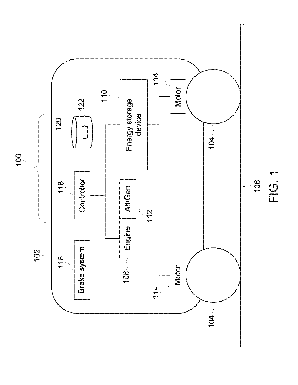
[0011]One or more embodiments of the inventive subject matter described herein provide hybrid vehicle systems and / or control systems for the hybrid vehicle systems. Through the use of the disclosed illustrative embodiments, it is possible to improve the efficiency in which a hybrid vehicle system operates while also reducing the size (and weight) of the engine and / or energy storage devices onboard the vehicle system. For example, the inventive subject matter described herein provides for a computerized system that works in conjunction with vehicular components and systems in order to improve the operation of a vehicle system that includes (and is propelled by) the vehicular components. Without the operation of the computerized systems described herein, the vehicle system may be required to have a larger (and heavier) engine, batteries, and the like, in order to complete some trips over routes within designated (e.g., previously scheduled) times. With operation of the computerized sy...


PUM


Abstract

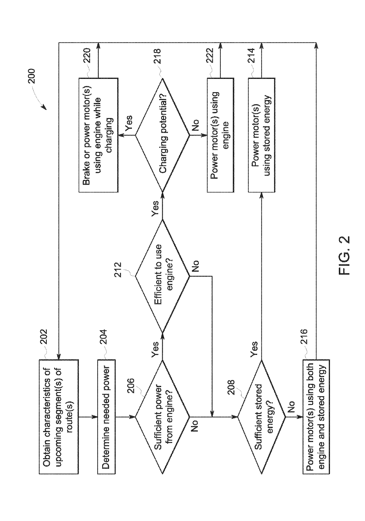
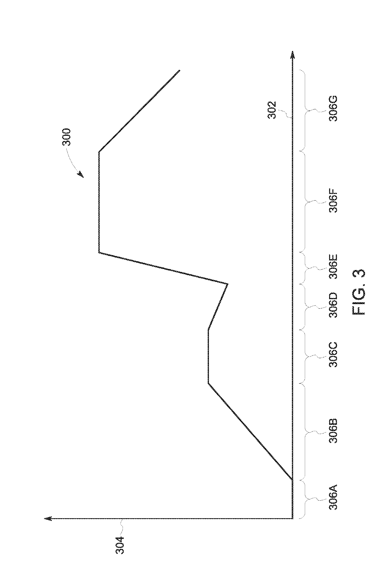
A vehicle control system examines characteristics of an upcoming segment of a trip of a hybrid vehicle. One or more locations in the upcoming segment of the trip are identified based on the characteristics as places where an engine of the vehicle is incapable of generating enough energy to power the vehicle through the locations. Operational settings of the vehicle are calculated based on the locations to operate the vehicle in a way that charges an energy storage device with energy that can be used to replace or supplement the energy provided by the engine to propel the hybrid vehicle over or through the locations. The one or more processors are configured to one or more of automatically control or generate a control signal for automated operation of the hybrid vehicle according to the one or more operational settings that are calculated.

Description

FIELD[0001]The subject matter described herein relates to hybrid vehicles, such as vehicles that are propelled by two or more distinct sources of motive power.BACKGROUND[0002]Some hybrid vehicles can be propelled by power provided by different sources, such as a fuel-consuming engine and batteries. The engine consumes fuel to drive the wheels of a vehicle, or to drive an alternator or generator (which generates electric current that powers motors to propel the vehicle). The batteries can store electric energy that powers the same or different motors to also propel the vehicle.[0003]One problem with some hybrid vehicles that are at least partially propelled by power from batteries is that the number and / or size of the batteries may add significant weight to the vehicles. This can result in reduced efficiency in operation of the engine and / or batteries to propel the vehicles. For example, as more batteries are added to a vehicle to reduce the amount of fuel that is consumed by the eng...

Claims


Application Information

Patent Timeline
IPC IPC(8): B60W20/12B60L15/20B60K6/46B60L11/18B60L11/12B60W20/14
CPCB60W20/12B60L15/2045B60K6/46B60W40/076B60L50/61B60L2200/26B61C7/04B60W40/072B60L58/12B60W20/14B60K6/52B60L7/10B60L2240/62B60L2240/642B60L2260/54B60W10/06B60W10/08B60W10/26B60W30/18127B60W50/0097B60W2710/244B61C9/24B60W2552/15B60W2552/20B60W2552/30B60W2556/50Y02T10/40Y02T10/62Y02T10/64Y02T10/70Y02T10/72Y02T10/84Y02T30/00Y02T90/16
Inventor LAVERTU, THOMAS MICHAEL
Owner GE GLOBAL SOURCING LLC
Learn More