
Delivery device for prosthetic mitral valve annuloplasty ring and prosthetic mitral valve annuloplasty ring delivery system

a technology of prosthetic mitral valve and delivery device, which is applied in the field of medical devices, can solve the problems of undesirable leaflet coaptation height, adversely affecting the annuloplasty outcome, and distortion of the normal shape of the valve orifice, and achieve the effect of improving the outcome of the mitral valve annuloplasty

Active Publication Date: 2019-08-15
SHANGHAI NEWMED MEDICAL CO LTD
View PDF0 Cites 1 Cited by
  • Summary
  • Abstract
  • Description
  • Claims
  • Application Information

AI Technical Summary

Benefits of technology

The present invention provides a device and system for delivering a prosthetic mitral annuloplasty ring to a target site in the heart. The device has a driving member and a connecting member that is connected to the distal end of the driving member. The device can be fixed to the prosthetic mitral annuloplasty ring and resized by rotating the adjustment member, which results in a change in the size of the ring. The device allows for improved outcomes by delivering a prosthetic mitral annuloplasty ring that can be resized according to the needs of the patient.

Problems solved by technology

Stretching of the mitral valve annulus may compromise the competence of the valve, leading to a distortion of the normal shape of the valve orifice.
A small size of the prosthetic mitral annuloplasty ring may cause mitral valve stenosis, while too large size of the prosthetic mitral annuloplasty ring can lead to undesirable leaflet coaptation height and areas which may adversely affect annuloplasty outcomes.
Since traditional mitral valve annuloplasty procedures require cardiopulmonary bypass with the heart arrested, it is difficult to accurately measure the size of the mitral annulus and assess the repair outcome.

Method used


Image

  • Delivery device for prosthetic mitral valve annuloplasty ring and prosthetic mitral valve annuloplasty ring delivery system
  • Delivery device for prosthetic mitral valve annuloplasty ring and prosthetic mitral valve annuloplasty ring delivery system
  • Delivery device for prosthetic mitral valve annuloplasty ring and prosthetic mitral valve annuloplasty ring delivery system

Examples


Embodiment Construction

[0030]The prosthetic mitral annuloplasty ring delivery device and system proposed in the present invention will be described in greater detail below with reference to specific embodiments which are to be read in conjunction with the accompanying drawings. Features and advantages of the invention will be more readily apparent from the following detailed description, and from the appended claims. Note that the figures are provided in a very simplified form not necessarily presented to scale, with the only intention of facilitating convenience and clarity in explaining the embodiments.

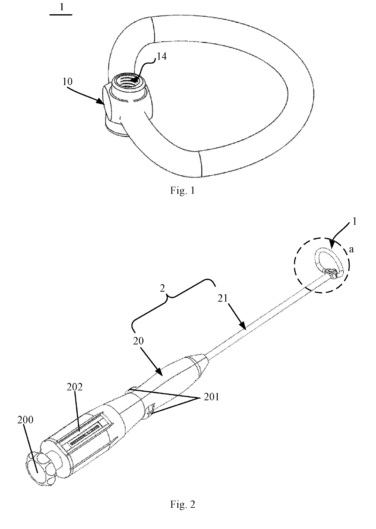
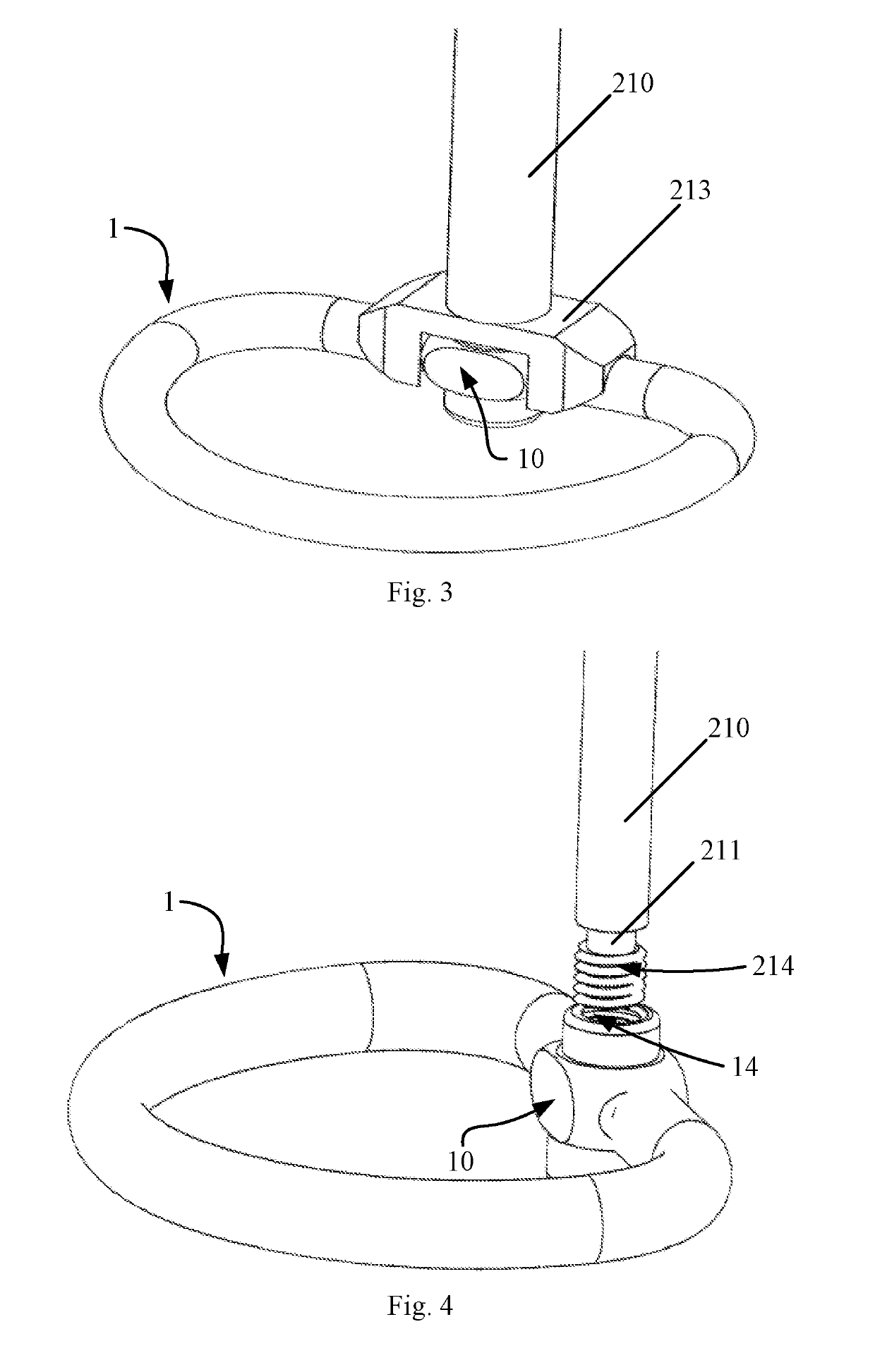
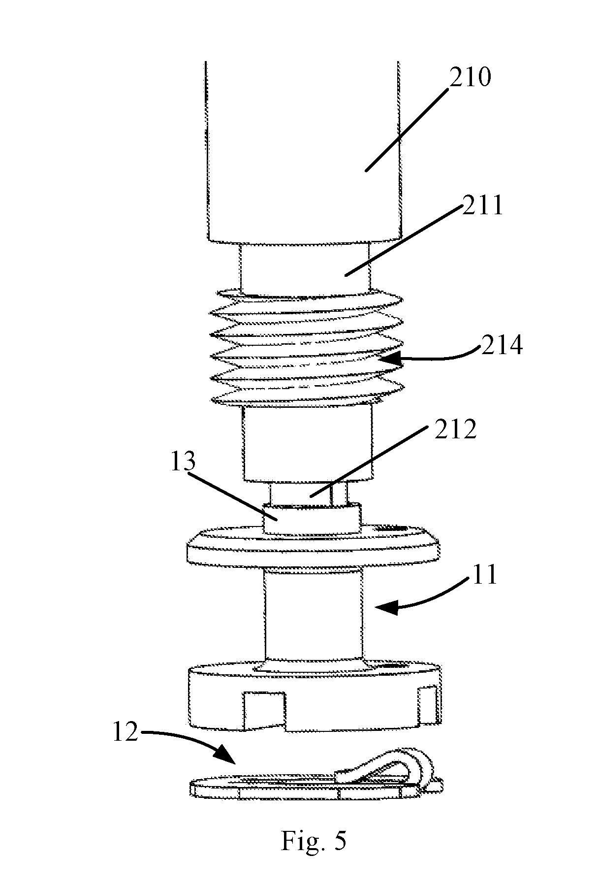
[0031]Disclosed herein is a device and system for a prosthetic mitral annuloplasty ring capable of repairing a defective mitral valve so that it regains its normal physiological shape and configuration. Reference is now made to FIGS. 1 and 2. FIG. 1 schematically shows a prosthetic mitral annuloplasty ring according to an embodiment of the invention, and FIG. 2 is a schematic illustration of a system for ...


PUM


Abstract

A prosthetic mitral annuloplasty ring includes a wire, an adjustment member for changing a length of the wire and a jacketing annulus for adjusting a radial dimension of the mitral valve annuloplasty ring. The jacketing annulus is sleeved over the wire and forms, together with the adjustment member, a shape matching that of a native mitral valve annulus. After the prosthetic mitral annuloplasty ring is implanted by suturing in a conventional surgical procedure and the patient's heart starts to beat again, the adjustment member can be connected to the delivery device and the wire length therein can be adjusted by a rotating operation of the delivery device so that the mitral valve annuloplasty ring will be expanded or contracted until the prosthetic mitral annuloplasty ring perfectly fits the native mitral valve annulus in shape, effectively avoiding the problem of incomplete mitral leaflet coaptation.

Description

TECHNICAL FIELD[0001]The present invention relates to medical devices and, in particular, to a delivery device for delivering a prosthetic mitral annuloplasty ring and a prosthetic mitral annuloplasty ring delivery system.BACKGROUND[0002]Mitral valve annuloplasty treats heart valve diseases featuring mitral valve regurgitation by implanting a prosthetic mitral annuloplasty ring. As part of the surgical technique, the prosthetic ring can help repair heart valve defects (e.g., incomplete mitral leaflet coaptation). The mitral valve consists of the mitral valve annulus, leaflets, papillary muscles and chordae tendineae. Mitral regurgitation is the abnormal leaking of blood backwards from the left ventricle into the left atrium, when the left ventricle contracts. Stretching of the mitral valve annulus may compromise the competence of the valve, leading to a distortion of the normal shape of the valve orifice.[0003]As key part mitral valve annuloplasty, the prosthetic mitral annuloplasty...

Claims


Application Information

Patent Timeline
Patent Type & Authority Applications(United States)
IPC IPC(8): A61F2/24
CPCA61F2/2466A61F2/2448A61F2002/9505A61F2/2427A61F2/2445
Inventor YU, QIFENGHOU, LIHONGWANG, ZHIJIEWANG, HAISHANQIN, TAO
Owner SHANGHAI NEWMED MEDICAL CO LTD
Learn More