
Method and device for inspecting a nuclear reactor part

a nuclear reactor and inspection method technology, applied in the direction of television systems, instruments, greenhouse gas reduction, etc., can solve the problems of time-consuming operation and the risk of collision with other pieces of equipment inside the vessel, and achieve the effect of accelerating the inspection method and reducing the risk of interference with other pieces of equipment of the reactor

Active Publication Date: 2019-08-01
FRAMATOME ANP
View PDF2 Cites 0 Cited by
  • Summary
  • Abstract
  • Description
  • Claims
  • Application Information

AI Technical Summary

Benefits of technology

The patent text describes an inspection method that speeds up the process and reduces the risk of interfering with other equipment in the reactor.

Problems solved by technology

Such an operation is time-consuming.
Furthermore, it involves multiple movements of the carrier, controlled remotely, which creates a risk of collision with other pieces of equipment inside the vessel.

Method used


Image

  • Method and device for inspecting a nuclear reactor part
  • Method and device for inspecting a nuclear reactor part
  • Method and device for inspecting a nuclear reactor part

Examples


Embodiment Construction

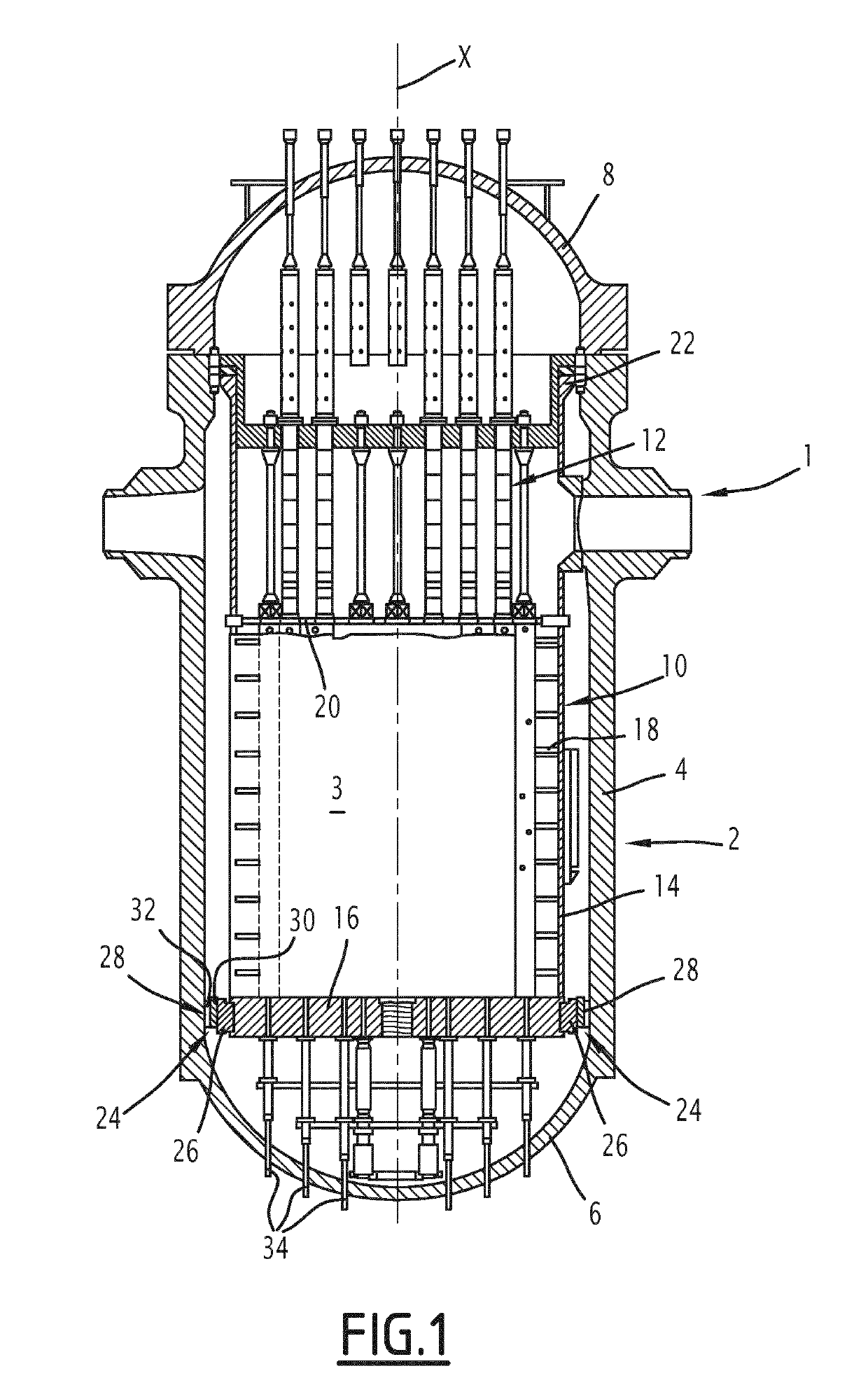
[0038]The method and the device according to the present disclosure are intended to inspect an area of a nuclear reactor part. Said nuclear reactor is for example a pressurized water reactor, with level 900 MW, as shown in FIG. 1.

[0039]The method and the device according to the present disclosure are also suitable for any other type of reactor, for example BWR, and all levels and types of PWR reactor.

[0040]The reactor 1 comprises a vessel 2, in which a core 3 is positioned. The core 3 includes a plurality of nuclear fuel assemblies, with a generally prismatic shape. The vessel has a central axis X, which is substantially vertical. The vessel comprises a substantially cylindrical shroud 4, a hemispherical lower bottom 6, closing a lower end of the shroud 4, and a removable cover 8, closing an upper end of the shroud 4.

[0041]The nuclear reactor 1 also comprises pieces of lower internal equipment 10 (IIE) and pieces of upper internal equipment 12, positioned inside the vessel 2. The pi...


PUM


Abstract

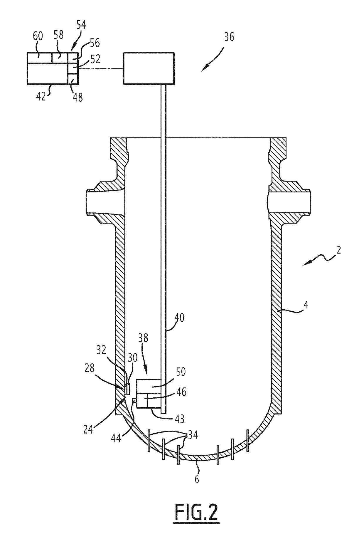
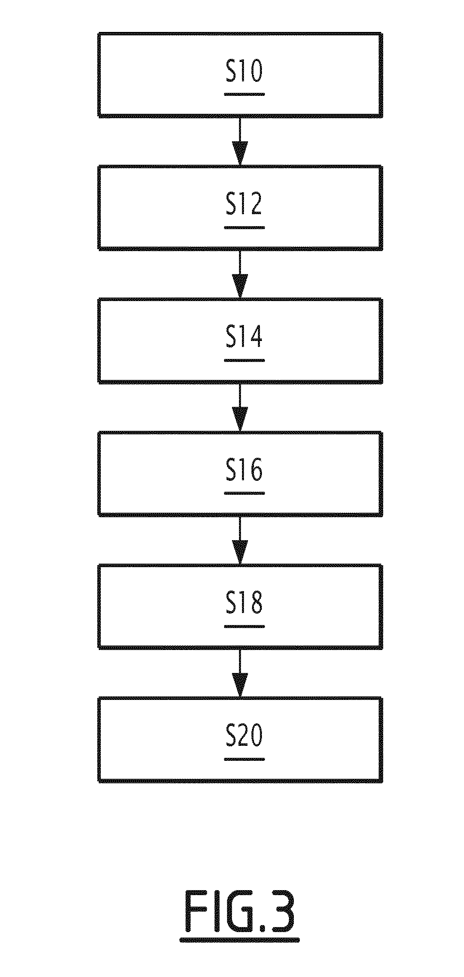
A method for inspecting a nuclear reactor part includes placing an optical sensor (38) in front of the part to be inspected using a carrier (40); acquiring at least a first image of at least a reference portion of the part using the optical sensor (38), the or each first image being taken with a first magnification; reconstituting a three-dimensional model of said reference portion of the part using the or each first acquired image; calculating the position of an area to be inspected relative to the optical sensor (38) using the three-dimensional model; acquiring at least a second image of the area to be inspected using the optical sensor (38), the or each second image of the area to be inspected being taken with a second magnification higher than the first magnification.

Description

[0001]The invention generally relates to the inspection of parts of a nuclear reactor.BACKGROUND[0002]During certain maintenance operations of the nuclear reactor, it is requested to visually inspect specific areas of parts located near the inside of the pressurized vessel of the nuclear reactor.[0003]These parts are for example the vessel bottom entries, or elements of the devices for keeping bottom internal equipment in position.[0004]To that end, it is possible to use a carrier that keeps a camera in position facing the part to be inspected.[0005]The control command device of the carrier allows placement of the camera with an error on the position that is frequently of several centimeters. To be able to inspect a precise location of the part, it is necessary to recalibrate the position of the camera. To that end, a corner of the part is for example used, when said part has one. The position of the camera is successively adjusted with respect to each of the three surfaces coming t...

Claims


Application Information

Patent Timeline
Patent Type & Authority Applications(United States)
IPC IPC(8): G21C17/08H04N5/232H04N5/225G06T17/00G06T7/73G21C17/007
CPCG21C17/08H04N5/232125H04N5/232133H04N5/2256G06T17/00G06T7/75G21C17/007G21C17/003Y02E30/30H04N23/56H04N23/676H04N23/959
Inventor CAULIER, YANNICK
Owner FRAMATOME ANP
Learn More