
Spool

a technology of spools and spools, which is applied in the field of spools, can solve the problems of material creases and the inability to smoothly intertwine the end part of the material with the groove, and achieve the effects of reducing avoiding material creases and dents in the winding process, and good pre-fixing

Active Publication Date: 2019-08-01
SUZHOU TIANYU PLASTIC
View PDF0 Cites 1 Cited by
  • Summary
  • Abstract
  • Description
  • Claims
  • Application Information

AI Technical Summary

Benefits of technology

This patent aims to create a spool that can prevent creases in material while winding it.

Problems solved by technology

In the process of winding the material by the spool, a few initial laps of the material are often dented by the end of the material, resulting in creases on the material.
However, in practical use, due to the unevenness of the end part of the material, the end part of the material cannot be smoothly intertwined with the groove.
Thus, there are still defects of dents caused by a gap between the end part and the groove in the winding process, which need to be improved.

Method used


Image

  • Spool
  • Spool
  • Spool

Examples


embodiment 1

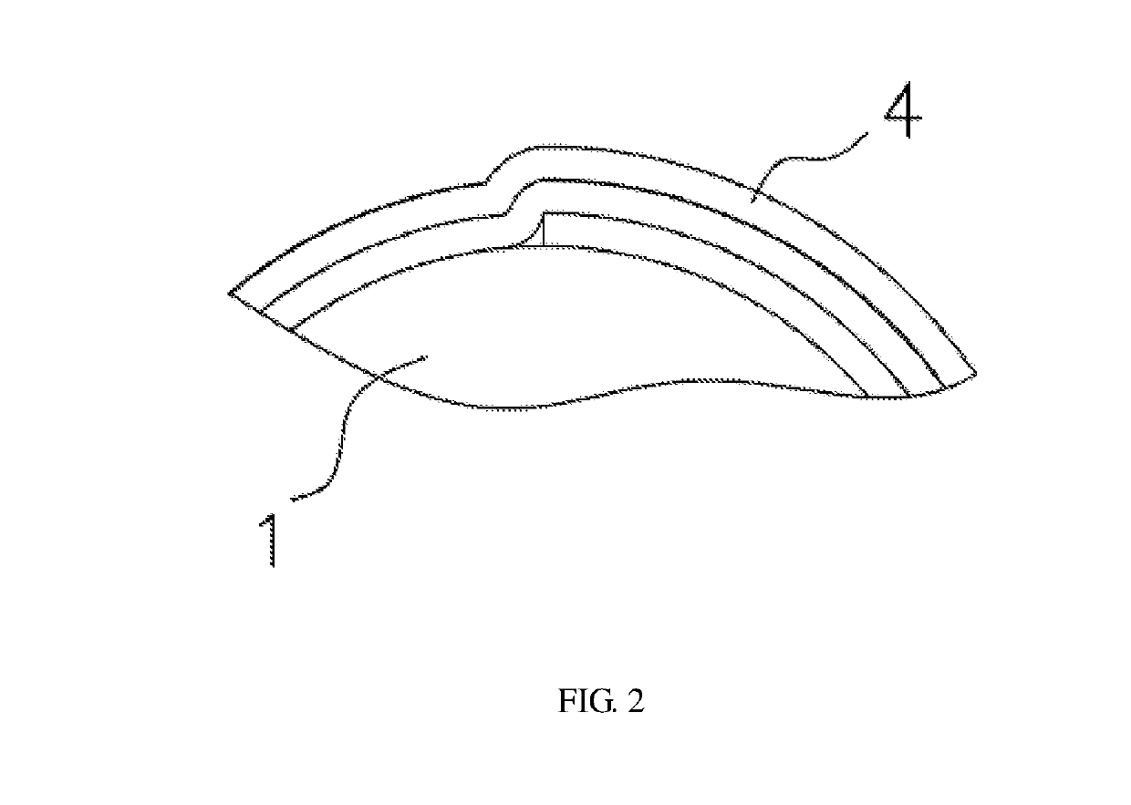
[0037] a spool is shown in FIG. 2, wherein the spool has a cylindrically continuous surface, when a material 4 such as a film is wound thereon, the terminal of the material 4 will dent some subsequent rolls of material 4terminal.

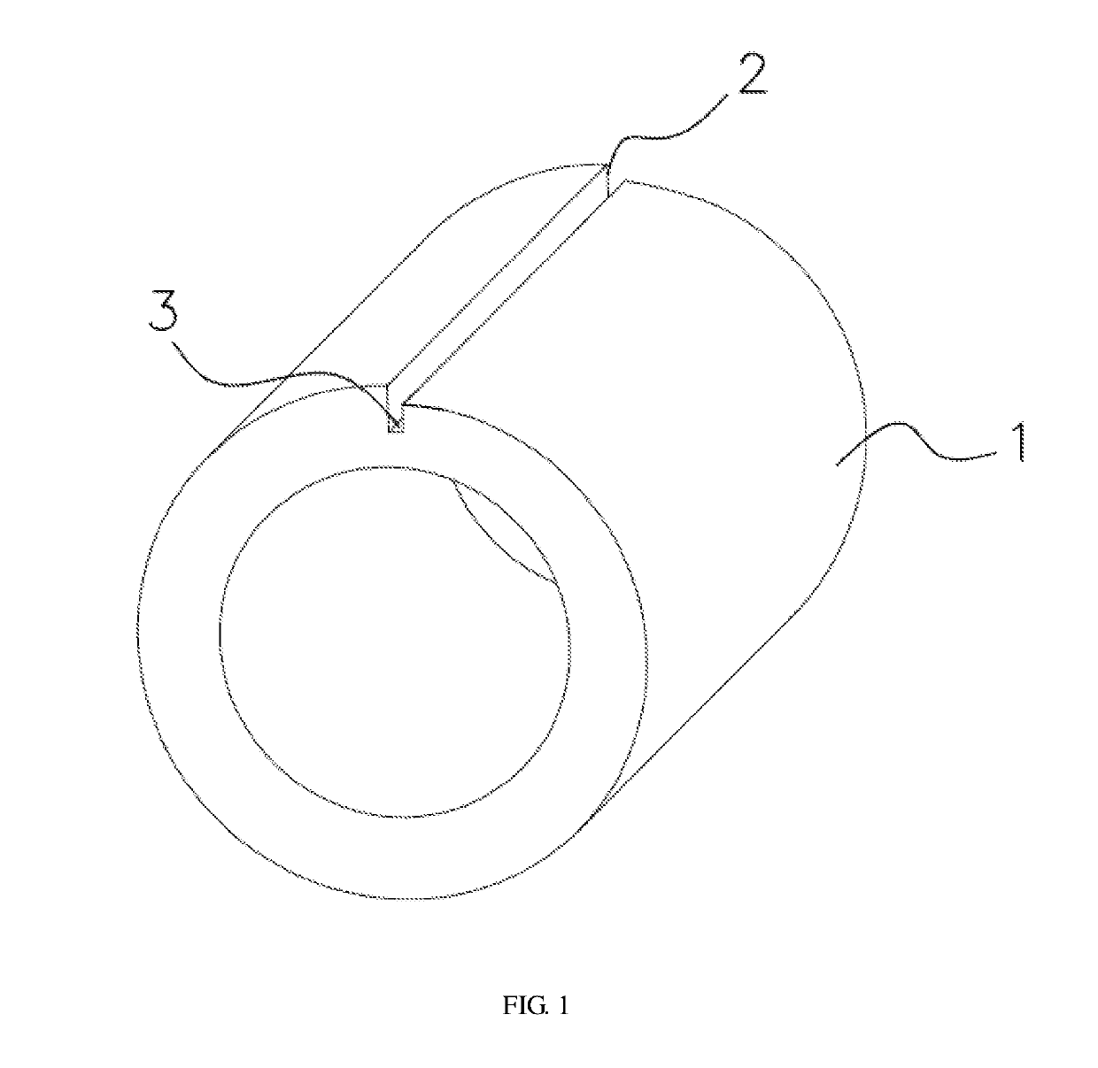
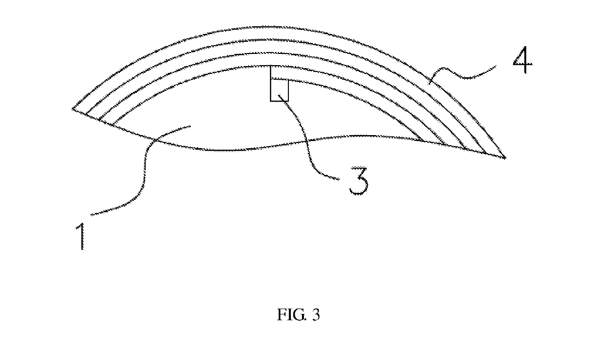
[0038]With reference to FIG. 3 of the description, a step portion 2 is disposed on the surface of the spool so that the diameter of the upper side of the step portion 2 is larger than the diameter of the lower side of the step portion 2. The height of the step portion 2 is set to the thickness of a film of the wound material 4. Thus, when the material 4 is paved on the lower side of the step portion 2, the outer surface of the material 4 is flush with the upper side of the step portion 2, so as to effectively eliminate such a conventional defect of dents and wrinkles.

[0039]With reference to FIG. 1 of the description, the step portion 2 is disposed on the surface of the spool along the axial direction of the spool. The lower side of the step portion 2 comes d...

embodiment 2

[0040] a spool is shown in FIG. 4 and FIG. 5 of the description, the spool includes a tube 1, a step portion 2 and a cutting groove 3. The cutting groove 3 has a width of 1-1.5 mm and a depth of 2 mm. A resilient clip 5 is disposed in the cutting groove 3. An extension 6 is integrally with and above the resilient clip 5. The resilient clip 5 has a thickness of 0.3-0.6 mm. The extension has a thickness of 0.8-1.2 mm. The thickness of the resilient clip 5 is less than the thickness of the extension 6. The strength of the extension 6 is larger than that of the resilient clip 5. The extension 6 is stably fixed to the tube 1 while the resilient clip 5 can be deformed. The resilient clip 5 and the extension 6 are generally formed into the shape of the figure “7”. The extension 6 is attached to the surface of the tube 1. The extension 6 has a tenon 7 inserted into a mortise 8 formed in the tube 1. The tenon 7 and the mortise 8 are engaged tightly. The extension 6 is fixed to the surface of...


PUM


Abstract

A spool includes a tube for winding a material. The outer surface of the tube is provided with a step portion along the axial direction thereof. The step portion is as high as the thickness of the material. A cutting groove is provided on a side, close to the axial centre of the tube, of the step portion. An resilient clip for clamping the material is fixed in the cutting groove, the upper end of the resilient clip is connected to a notch on one side of the cutting groove, and the lower end thereof is inclined towards the other side of the cutting groove. The spool positions a cutter by means of the cutting groove, and the resilient clip clamps the cut material in the cutting groove.

Description

TECHNICAL FIELD[0001]The utility model relates to a winding tool, and particularly relates to a spool.BACKGROUND ART[0002]A spool is a component used to collect various films, tapes or papers and other soft and long material. In the process of winding the material by the spool, a few initial laps of the material are often dented by the end of the material, resulting in creases on the material. In the fields of optical films and the like which have high requirements for surface material, the material is often discarded.[0003]To overcome the above problems, a spool is disclosed by the applicant in a Chinese utility model patent with a filing date of Mar. 21, 2011 and an application number of CN201120074757.7. The spool includes a tube used to wind material to be wound. A groove is formed in an outer surface of the tube. The groove has a vertical surface, and a bottom surface of the groove is in smooth connection with the outer surface of the tube.[0004]In the above structure, the groo...

Claims


Application Information

Patent Timeline
Patent Type & Authority Applications(United States)
IPC IPC(8): B65H75/28B65H75/32
CPCB65H75/28B65H75/32B65H2701/53
Inventor QIAN, XIAOREN
Owner SUZHOU TIANYU PLASTIC
Learn More