
Projectile comprising a device for deploying a wing or fin

Active Publication Date: 2019-07-18
NEXTER MUNITIONS
View PDF0 Cites 4 Cited by
  • Summary
  • Abstract
  • Description
  • Claims
  • Application Information

AI Technical Summary

Benefits of technology

The invention is a new type of missile that has wings or fins that are placed in the middle of its body to help it fly better. The deployment of these wings is controlled by a single engine that is connected to an expansion system. The device also has a mechanism to prevent the wings from spinning too much during the second deployment phase. The result is that the missile is lighter and more stable during flight.

Problems solved by technology

This mechanism therefore requires space and its complexity can cause malfunctions or incomplete deployments.
The documents mentioned above have, however, drawbacks that may affect the good stabilization ensured by the fins.
Thus, if the projectile is inclined during the second deployment phase, the fins being each subjected to different aerodynamic forces, it is not certain that the fins are deployed correctly, thereby making unreliable the deployment mechanisms or devices taught in the documents above.

Method used


Image

  • Projectile comprising a device for deploying a wing or fin
  • Projectile comprising a device for deploying a wing or fin
  • Projectile comprising a device for deploying a wing or fin

Examples


Embodiment Construction

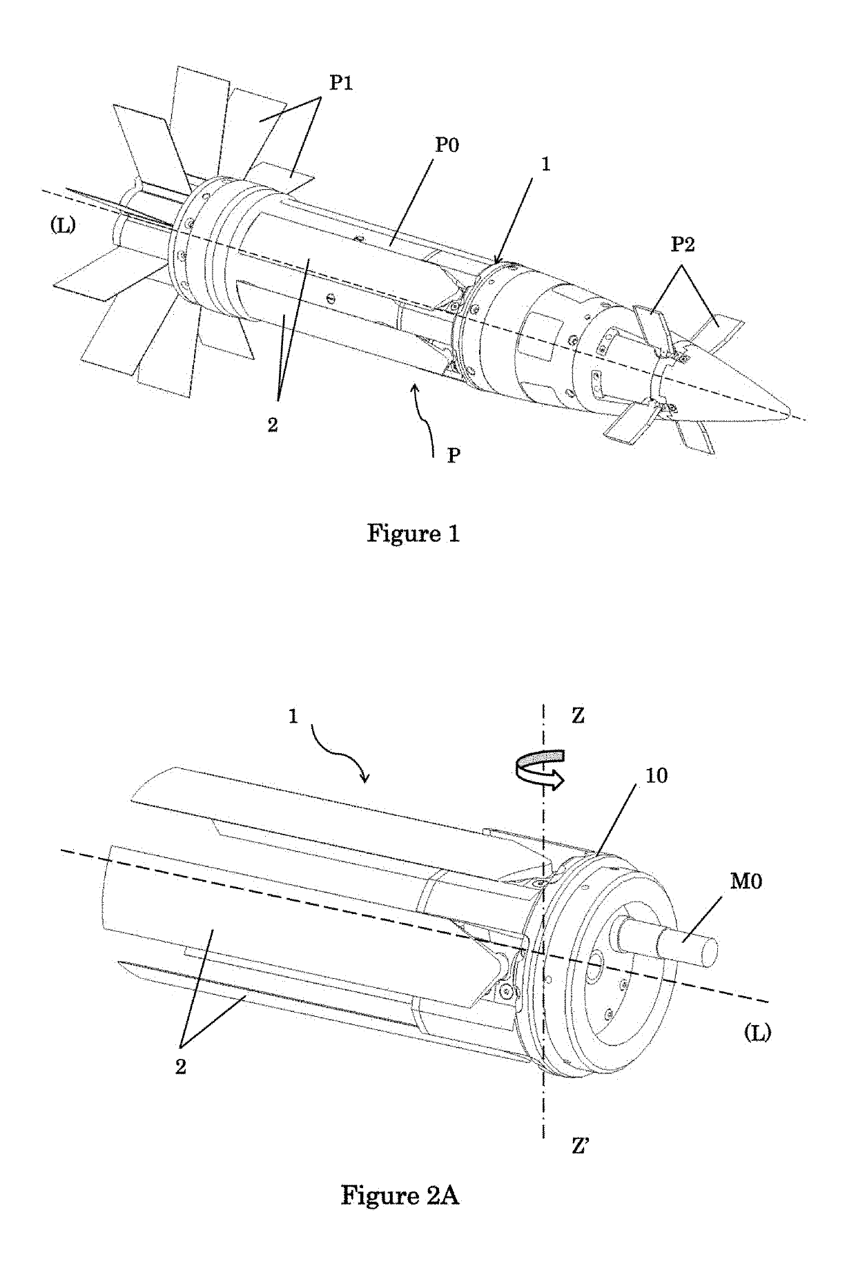
[0030]The present invention relates to a projectile (P) and to the wing or fin deployment device (1) [FIG. 1] associated therewith to ensure its stabilization in the flight phase.

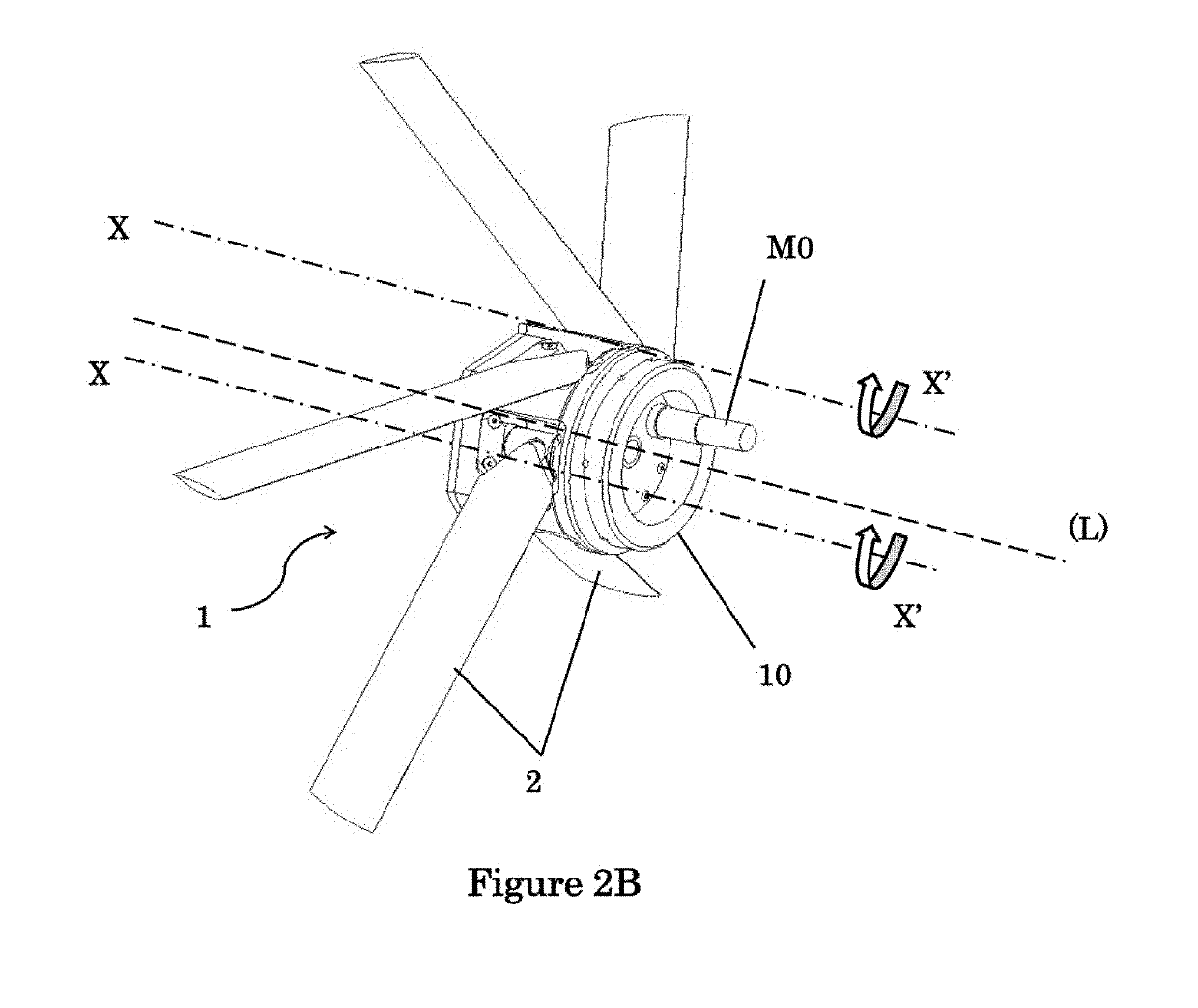
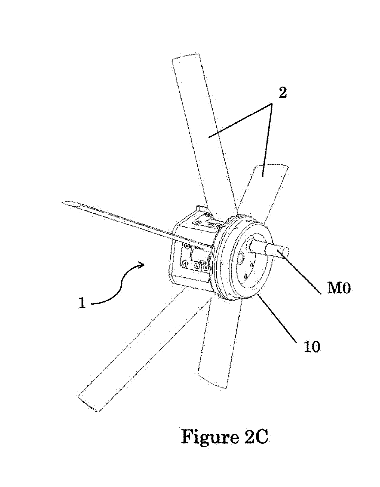
[0031]In some embodiments, the projectile (P) includes a body (P0) having a longitudinal axis (L) and an intermediate portion comprising a device (1) for deploying wings (2) or fins including a number N, preferably equal to at least three, of wings (2) or fins able to be deployed, said wings being evenly distributed angularly around the axis (L) of the projectile. The deployment method comprises at least two phases, a first deployment phase in which a wing (2) or fin switches from a position tangential to the body (P0) of the projectile and parallel to the longitudinal axis (L) (FIG. 2A) to a semi-deployed position (FIG. 2B), by rotation of the wing (2) or fin around a axis (ZZ′) perpendicular to the longitudinal axis (L) of the projectile (P) and a second deployment phase with the switching of the wing (2)...


PUM


Abstract

The present invention relates to a projectile including a body having a longitudinal axis and an intermediate portion comprising a wing or fin deployment device including at least a number N, at least equal to three, of wings or fins able to be deployed, the deployment method comprising at least two phases, a first deployment phase in which each wing or fin switches from a position tangential to the body of the projectile and parallel to the longitudinal axis to a semi-deployed position, and a second deployment phase with the switching of each wing from the semi-deployed position to a deployed position in which it is perpendicular to the body of the projectile, said wing deployment device is configured to synchronize the deployment of wings or fins in the second phase.

Description

TECHNICAL FIELD OF THE INVENTION[0001]The present invention relates to the field of exterior ballistics and more particularly to the stabilization of projectiles moving in space. More specifically, the invention relates to a projectile and its associated wing or fin deployment device.TECHNOLOGICAL BACKGROUND OF THE INVENTION[0002]During a projectile firing, several parameters are to be taken into account for said projectile to reach a designated target. During the flight phase, the projectile is subjected to aerodynamic forces that can deflect it from its trajectory. One of the important parameters is thus the stabilization of said projectile.[0003]For their stabilization, several projectiles are, to this end, provided with wings or fins deployment mechanisms or devices. The association of such a mechanism or device with the projectile, however, should not cause a significant variation in the dimensions of the architecture of the projectile at the risk of either aggravating the aero...

Claims


Application Information

Patent Timeline
IPC IPC(8): F42B10/14
CPCF42B10/14F42B10/02
Inventor PINOTEAU, SYLVAIN
Owner NEXTER MUNITIONS
Learn More